


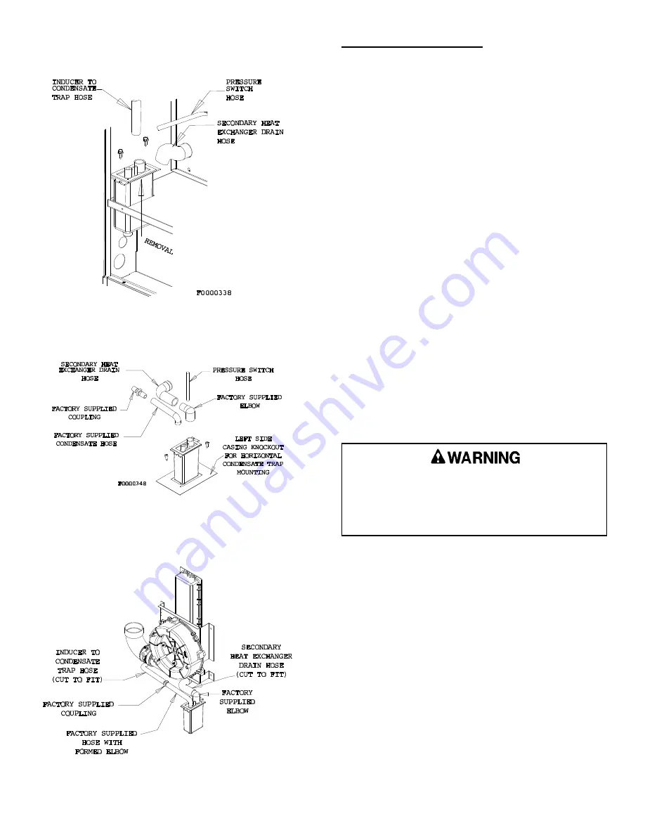
Figure 21
UPFLOW TRAP
Figure 22
HORIZONTAL TRAP
Figure 23
HORIZONTAL LEFT CONDENSATE TUBING
Condensate Disposal Drain:
This furnace must use the condensate trap supplied
with the unit (See Figures 17 and 18) for proper drain
installation. The drain must terminate at a floor drain,
sewer system, or drain vent for proper condensate
removal. Drain installation must conform to local building
codes.
In addition, the trap must be filled with water on the
initial start-up of the unit. Installation location may require
that the trap be filled at the beginning of each heating
season. Filling the trap should be accomplished by: 1)
disconnecting the inducer outlet coupling hose from the
inducer outlet coupling, 2) pouring approximately 12 oz.
of tap water into the inducer outlet coupling hose and 3)
reconnecting the inducer outlet coupling hose to the
inducer outlet coupling.
When terminating the condensate disposal into a
condensate pump, the condensate drain should not be
submerged into the pump.
Do not connect the condensate drain to a positive
pressure such as an A/C coil drain. If connecting to a
common A/C coil drain special pressure relieving means
must be taking. (ie. atmospheric vent install between the
two traps).
In addition, if this unit is placed in an unconditioned
space such as an attic or crawlspace where local
plumbing code would require potable water supply piping
to be protected;
a thermostatically controlled heat tape
must be installed along the entire length of
condensate drain in the unconditioned space.
Failure to install a heat tape on condensate drain
lines in unconditioned spaces could lead to
nuisance furnace shut-down, water damage, and/or
a hazardous condition which may lead to bodily
harm, or loss of life.
20558801
Issue 0442
Page 18 of 32
Содержание Gas-Fired Furnace
Страница 13: ...FURNACE WIRING SPECIFICATIONS 20558801 Issue 0442 Page 5 of 32 ...
Страница 21: ...Figure 8 20558801 Issue 0442 Page 13 of 32 VENT TERMINATION CLEARANCES ...
Страница 36: ...SEQUENCE OF OPERATION DIRECT IGNITION SYSTEM CONTROL 20558801 Issue 0442 Page 28 of 32 ...
Страница 40: ...WIRING DIAGRAM 20558801 Issue 0442 Page 32 of 32 ...


