background image

LCX


RG66010687_rev.00 


33


10  ROUTINE MAINTENANCE AND CHECKS 


10.1 WARNINGS 


For safety reasons concerning installation, the right measures and precautions 
should be taken to prevent the ambient temperature from rising above 50°C 
whether the machine is switched on or off. 


All the operations described in this chapter MUST ALWAYS BE PERFORMED BY 
QUALIFIED PERSONNEL. 


Before carrying out any work on the unit or accessing internal parts, make sure 
you have disconnected it from the mains electricity supply. 


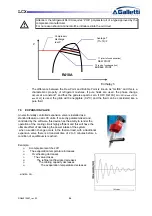
The upper part and outlet pipe of the compressor may reach temperatures as high 
as 110°C. Be especially careful when working in the surrounding area while the 
unit is running. 


Be especially careful when working in proximity to finned coils since the 0.11 mm-
thick aluminium fins can cause superficial injuries due to cuts. 


After completing maintenance work, always place the panels enclosing the units 
back and secure them with the fastening screws provided. 


For the safety of the person conducting maintenance work on the LCX units it is 
compulsory to turn the main switch off before performing said maintenance work. 
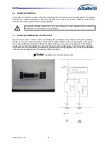
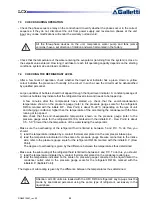
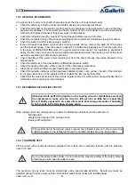
Access to the fan compartment has been fitted with a second safety panel (see 
fig.) with the sign “warning! moving parts” in order to prevent injuries caused by 
the fans while they are running with the unit in operation. 


Rear of the LCX unit 


Содержание LCX Series

Страница 1: ...LCX Installation use and maintenance manual COOLING ONLY HEAT PUMP AND FREE COOLING VERSIONS USER MANUAL ...

Страница 2: ...G66010687_rev 00 2 For further information or communication please contact the company at info galletti it To find out the weight of each unit please refer to the table in the paragraph Rated specifications ...

Страница 3: ...L CONNECTIONS 17 6 1 GENERAL INFORMATION 17 6 2 FLOW SWITCH ON THE WATER SIDE 18 6 3 ELECTRIC CONNECTIONS OF THE CIRCULATION PUMP 18 6 4 REMOTE CONTROLS 19 6 5 REMOTE SUMMER WINTER SWITCHING 19 7 START UP 21 7 1 PRELIMINARY CHECKS 21 7 2 STARTING OPERATIONS 22 7 3 CHECKS DURING OPERATION 23 7 4 CHECKING THE REFRIGERANT LEVEL 23 7 5 EXPANSION VALVE 24 7 6 STOPPING THE UNIT 25 8 OPERATING LIMITS 25 ...

Страница 4: ... OF THE COOLING CIRCUIT 35 10 6 CHARGING WITH R410A REFRIGERANT 35 10 7 ENVIRONMENTAL PROTECTION 36 11 DECOMMISSIONING THE UNIT 36 12 TROUBLESHOOTING 37 13 WATER PRESSURE DROPS 41 13 1 PRESSURE DROPS IN EVAPORATOR 41 13 2 PRESSURE DROPS IN HEAT RECUPERATOR 41 13 3 PRESSURE DROPS IN FREE COOLING FINNED PACK HEAT EXCHANGERS 41 14 TECHNICAL DATA SUMMARY 42 15 DIMENSIONAL DRAWINGS 54 16 SUMMARY TABLE ...

Страница 5: ...X RG66010687_rev 00 5 Declaration of conformity The declaration of conformity is enclosed as a separate document with the papers supplied with the machine usually placed inside the electric control board ...

Страница 6: ... finned block heat exchangers 35 C Example of product code composition Configurations Chiller cooling only C Heat pump H Versions Standard version S Low noise version for a low noise impact L Quiet version for an extremely low noise impact Q Efficiency Packs Efficiency pack 1 1 compressor per circuit Efficiency pack 2 2 tandem compressors on 1 circuit Efficiency pack 4 2 tandem compressors on 2 ci...

Страница 7: ...CX194HS HL HQ 187 LCX214CS CL CQ 209 LCX214HS HL HQ 209 LCX244CS CL CQ 237 LCX244HS HL HQ 237 LCX274CS CL CQ 271 LCX274HS HL HQ 271 LCX294CS CL CQ 296 LCX294HS HL HQ 296 LCX324CS CL CQ 314 LCX324HS HL HQ 314 LCX364CS CL 355 LCX364HS 355 FREE COOLING Fluid chillers with Free Cooling exchange designed to cool water or mixtures of water and an antifreeze agent intended for civil air conditioning and ...

Страница 8: ...ater and glycol solutions up to a maximum of 35 the weight in civil industrial and technological air conditioning environments Their use is recommended within the functioning limits carried in this manual or else the warranty attached to the sales contract would cease 3 GENERAL INFORMATION When installing or servicing the chiller you must strictly follow the rules provided in this manual comply wi...

Страница 9: ...LY BY QUALIFIED PERSONNEL AUTHORISED BY GALLETTI S P A SEE ANNEX FAILURE TO COMPLY WITH THE RULES PROVIDED IN THIS MANUAL OR ANY MODIFICATION MADE TO THE UNIT WITHOUT PRIOR AUTHORISATION WILL RESULT IN THE IMMEDIATE INVALIDATION OF THE WARRANTY Attention Before performing any kind of work on the unit make sure it has been disconnected from the power supply ...

Страница 10: ...nit is being unloaded and positioned utmost care must be taken to avoid abrupt or violent movements The unit must be handled carefully and gently avoid using machine components as anchorages when lifting or moving it The unit should be lifted using Ø1 GAS steel pipes at least 3mm thick to be inserted in the round holes provided on the base side members see fig below and identified by means of stic...

Страница 11: ...ndenser coils a speed of 8 m s 28 8 km h already generates a sufficient stagnation pressure to guarantee approx 60 of the nominal air flow rate In situations where the action of air currents is inevitable and there is a simultaneous presence of temperatures below 5 C the control of condensation for low outdoor temperatures must be of the flooding type or with a device for choking the condensing ex...

Страница 12: ...o guarantee the following clearances see figure on this page rear side plumbing connections min 1 0 metre to guarantee access to plumbing connections and or for any necessary maintenance on the pumps tank expansion tank flow switch and 3 way free cooling valve electric control board side min 1 0 metre to guarantee access for inspection and or maintenance of cooling components finned pack heat exch...

Страница 13: ...control on the water side allows to assess the correct functioning of the expansion tank and to detect water leakage in advance sumps on inlet and outlet piping for temperature detection for a direct view of operating temperatures They can also be consulted on the microprocessor on board the unit cut off valves gate valves to isolate the unit from the hydraulic circuit metal net filter compulsory ...

Страница 14: ...nected from the power supply On the FS FL versions it is compulsory to use glycol solutions max 35 weight in order to prevent damage to the finned coil caused by freezing which is very difficult to repair Carefully assess the minimum air T to which the unit may be exposed and then determine the of antifreeze to be added Failure to use anti freezing solutions may cause serious damage of the free co...

Страница 15: ...e set up in such a way as to guarantee that the nominal flow rate of the water supplied to the evaporator remains constant 15 in all operating conditions The compressors often work intermittently since the chilling requirements of the user generally do not coincide with the output of LCX unit In systems containing little water where the thermal inertia of the water is lower it is a good idea to ch...

Страница 16: ...p s kit Attention During hydraulic connection operations never work with open flames near or inside the unit 5 4 PROCEDURE FOR FILLING THE TANK The tank has not been designed to withstand a depression greater than 0 15 Bar For this reason attention should be paid to ensure that the pressure on the pump intake side where the expansion tank is positioned will always be greater than 0 5 bars while th...

Страница 17: ...ch 1 is set at the PS maximum admissible pressure of the system while pressure switch 2 will have the setting PS x 0 9 in accordance with the reference technical standard 6 ELECTRICAL CONNECTIONS 6 1 GENERAL INFORMATION Before carrying out any work on electrical parts make sure the power supply is disconnected Check that the mains electricity supply is compatible with the specifications voltage nu...

Страница 18: ...tion panel and swap over two phases then repeat the operation IN NO CASE SHOULD YOU TAMPER WITH THE WIRING DOWNSTREAM FROM THE MAIN SWITCH since this may alter the correct sequence of other devices e g pump s Close the fuse carriers F1 and F2 of the compressors F1 F2 F3 F4 in the case of LCX 4 compressor models Close the electrical control board and lock it by means of the turn locks An earth conn...

Страница 19: ...E SUMMER WINTER SWITCHING If you wish to include a remote control for switching the unit between the summer and winter operating modes you must remove the jumper between the contacts indicated in the wiring diagram and connect the remote switching control to the terminals themselves see annexed wiring diagram The switching modes vary according to whether the microprocessor control is of the basic ...

Страница 20: ...LCX RG66010687_rev 00 20 pCO available on all versions ...

Страница 21: ...ved it will not enable the machine to start Make sure there are no refrigerant leaks that may have been caused by accidental impacts during transport and or installation Check the power supply of the crankcase heating elements where present The heating elements must be turned on at least 12 10 minutes before the unit is started This function is carried out automatically when the main switch is off...

Страница 22: ...mode from the control panel red button heating green button cooling and press the ON button on the control panel The unit will start up if enabled by the safety devices of the water circulation pump s by the flow switch or differential pressure switch by the T sensor measuring the temperature of the water returning from the system chiller inlet and no alarms have been triggered Start up Check that...

Страница 23: ...ut 16 22 C depending on the type of unit and charging conditions higher than the temperature of the air entering the condenser with the fans running at top speed Also check that the end of evaporation temperature shown on the pressure gauge refer to the pressure gauge scale for the refrigerant R410A marked with the initials D P Dew Point is about 3 5 5 0 C lower than the temperature of the water l...

Страница 24: ...sion valve is installed as a standard feature on all LCX units If correctly parameterised and controlled by the software this device has the ability to render the operation of the cooling circuit highly efficient and this will have the ultimate effect of decreasing the power intake of the system when a sudden change occurs in the thermal load with a traditional expansion valve there is a transient...

Страница 25: ...TING LIMITS Operating limits of LCX chillers on COLD ONLY mode Cold only units Min Max Evaporator outlet water temperature C 5 15 External air temperature C 10 49 To operate with outdoor temperatures below 20 C it is essential to employ the optional device to monitor condensation Monitoring via fan speed modulation with a cutting phase regulator for 15 C T outside air 20 C Operating limits of LCX ...

Страница 26: ...ating function desired is maintained The problem about poor lubrication lacking adequate crankcase heating occurs mostly after breaks where due to the effect of the suction effect of the compressor the pressure in the slump suddenly falls and most of the refrigerant previously dissolved in the oil evaporates With no heating elements this would lead to two problems Oil dilution and therefore inadeq...

Страница 27: ...ficient to cover the entire thermal requirements T1 and T3 temperatures are always controlled by the microprocessor on board the unit to assess any faults to the free cooling 3 way valve for instance in free cooling mode with a switch valve and T1 and T3 are the same it means that the valve is blocked In the event of faults occurring in the free cooling mode it is possible to decide whether to onl...

Страница 28: ...re Condensing coils are fitted with a special partialization circuit that reduces the surface of thermal exchange and therefore allowing the unit to operated with the full air flow rate fig 7 Indeed both sections of the coils are usually operative in the mechanical only cooling mode but when the Free Cooling mode therefore with T2 of the outside air below T1 Delta T C in the event of a simultaneou...

Страница 29: ...uent authorisation in writing 8 3 EXTERNAL AIR TEMPERATURE The units are designed and built to work with outdoor air temperatures ranging from 10 with condensation control to 45 C applications outside the specified limits may be authorised by Galletti S p A subject to verification and subsequent authorisation in writing On request the units may be equipped with an electric heating element to heat ...

Страница 30: ...ETTING OF CONTROL DEVICES LCX C SERIES CONTROL DEVICE SET POINT DIFFERENTIAL Service thermostat CS CL CQ C 12 4 LCX H SERIES CONTROL DEVICE SET POINT DIFFERENTIAL Service thermostat CS CL CQ C 12 4 Service thermostat HS HL HQ C 40 4 LCX F SERIES CONTROL DEVICE SET POINT DIFFERENTIAL Service thermostat FS FL CQ C 12 4 Free Cooling activation temperature C System return temp 3 C ...

Страница 31: ...29 Maximum defrost time s 360 Minimum time between two defrosts s 1800 LCX F SERIES CONTROL DEVICE ACTIVATION DIFFERENTIAL RESETTING Antifreeze thermostat C 4 1 Automatic Maximum safety pressure switch bar 45 13 5 Manual Maximum safety pressure switch bar 40 5 12 2 Manual Low pressure safety valve bar 29 Minimum pressure switch bar 1 5 1 0 Automatic Modulating condensation control bar 18 10 Time b...

Страница 32: ... indicated by the set differential see Table II however the unit will not resume operation until the alarm memory on the microprocessor control is cleared 9 4 SERVICE THERMOSTAT The function of this device is to start and stop the compressors according to the demand for chilled water as determined by a sensor placed at the evaporator inlet water returning from the system This device is a function ...

Страница 33: ... high as 110 C Be especially careful when working in the surrounding area while the unit is running Be especially careful when working in proximity to finned coils since the 0 11 mm thick aluminium fins can cause superficial injuries due to cuts After completing maintenance work always place the panels enclosing the units back and secure them with the fastening screws provided For the safety of th...

Страница 34: ...where present of the compressor crankcases Clean the metal mesh filters mounted externally on the water pipes Check the humidity indicator on the liquid level indicator green dry yellow humid if the indicator is not green as shown on the indicator sticker replace the filter every 6 months Check that the noise emissions of the unit are regular every 6 months and more specifically that no vibrations...

Страница 35: ... the step described above Carry out the step described above for the third time but in this case attempting to reach the hardest vacuum possible Using this procedure you can easily remove up to 99 of pollutants 10 6 CHARGING WITH R410A REFRIGERANT Connect the tank of refrigerant gas to the male 1 4 SAE inlet situated on the liquid line after discharging a little gas to eliminate air in the connect...

Страница 36: ...ore special care should be taken when carrying out maintenance work to minimise refrigerant leaks 11 DECOMMISSIONING THE UNIT When the unit has reached the end of its working life and needs to removed and replaced a series of operations should be carried out the refrigerant gas it contains should be recovered by specialised personnel and sent to a waste collection facility the lubricating oil in t...

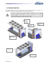
Страница 37: ... You should be extremely careful when attempting to implement any of the possible remedies suggested overconfidence can result in injuries even serious ones to inexpert individuals Therefore once the cause has been identified you are advised to contact the manufacturer or a qualified technician for help Dehydrating filter Expansion valve Hydronic unit tank pumps Plate exchanger evaporator Water in...

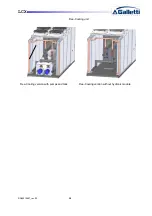
Страница 38: ...LCX RG66010687_rev 00 38 Free Cooling unit Free Cooling version with pumps and tank Free Cooling version without hydronic module ...

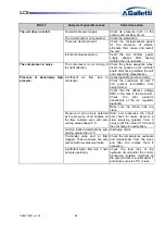
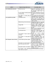
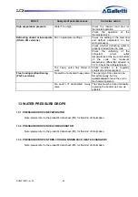
Страница 39: ...ndenser air inlet T and prevent recirculation from being formed Check that the effective voltage RMS to the fans is the maximum Check the pilot pressure transducers of the rev regulator optional Make sure the finned coils are clean Presence of air in circuit detected by the presence of air bubbles on the flow indicator even with sub cooling values above 5 C Drain and pressurise the circuit and che...

Страница 40: ...he filter should not exceed 2 C If they do replace the filter Low condensation T Make sure the condensation control works properly if present Low refrigerant load Check the refrigerant level by measuring the degree of subcooling if it is below 2 C top up the unit Coil frosted if heat pump is operating Check the correct defrost parameter settings Make sure the 4 way valve works properly Low outside...

Страница 41: ...refrigerant level The 4 way valve has failed to work Check whether it is regularly energized and deenergized Free Cooling malfunctioning FS FL versions No switch of activated 3 way valve The opening of the valve can be forced manually but it is recommended to leave the unit in mechanical operation No switch of deactivated 3 way valve The valve must be closed manually replacing the booster as soon ...

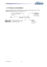
Страница 42: ...Table par 1 and the size of the unit L C X 1 0 4 H Q Efficiency Pack 4 2 tandem compressors on 2 circuits Efficiency Pack 2 2 tandem compressors on 1 circuit Efficiency Pack 1 1 compressor per circuit Approximate unit size in terms of cooling capacity 100kW in this case Range Configuration C cooling only H heat pump F free cooling Version Standard S Low noise L Quiet Q ...

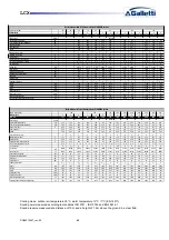
Страница 43: ... version 90 100 120 Approx capacity kW 170 190 210 240 270 290 320 360 Efficiency Pack 1 2 4 1 2 4 4 4 4 4 4 4 4 4 LCX CS 141 142 144 161 162 164 174 194 214 244 274 294 324 364 Power supply V ph Hz Cooling capacity UNI14511 kW 144 144 143 160 160 152 162 183 201 245 263 293 327 354 Total cooling power input UNI14511 kW 50 9 50 9 50 8 58 9 58 9 56 4 58 1 65 6 76 4 95 8 90 5 104 119 138 Rated curre...

Страница 44: ...50 49 52 52 49 Base unit operating weight kg 525 525 630 635 700 905 905 980 0 915 915 980 0 1260 1260 1275 Unit with pump and full tank operating weight kg 862 862 982 987 1067 1426 1426 1557 1436 1436 1557 2040 2040 2055 Rated technical data of LCX water chillers LOW NOISE version 120 90 100 400 3N 50 Approx capacity kW 170 190 210 240 270 290 320 360 Efficiency Pack 1 2 4 1 2 4 4 4 4 4 4 4 4 4 ...

Страница 45: ...essure level dB A 43 43 45 45 45 47 47 46 47 47 46 48 48 45 Base unit operating weight kg 525 525 630 635 700 905 905 980 0 915 915 980 0 1260 1260 1275 Unit with pump and full tank operating weight kg 862 862 982 987 1067 1426 1426 1557 1436 1436 1557 2040 2040 2055 Rated technical data of LCX water chillers QUIET super low noise version 90 100 400 3N 50 120 Approx capacity kW 170 190 210 240 270...

Страница 46: ... 3 58 3 64 3 51 3 55 3 52 3 52 3 52 3 50 3 52 Maximum current input A 60 64 75 91 91 101 101 119 119 120 Starting current A 195 192 200 261 261 269 269 319 319 247 Starting current with Soft Starter kit A 120 133 148 199 199 207 207 254 254 172 No of scroll compressors circuits 2 1 2 1 2 1 2 2 2 1 2 2 2 1 2 2 2 1 4 2 No of axial fans 4 4 4 6 6 6 6 8 8 8 Air flow rate m 3 h 21379 21379 21379 30913 ...

Страница 47: ...input A 131 131 129 137 144 150 136 155 173 196 224 237 251 300 Starting current A 330 330 245 389 396 266 252 310 330 380 403 468 476 497 Starting current with Soft Starter kit A 265 265 186 306 306 214 200 248 268 215 338 385 393 360 No of scroll compressors circuits 2 2 2 1 4 2 2 2 2 1 4 2 4 2 4 2 4 2 4 2 4 2 4 2 4 2 4 2 No of axial fans 8 8 8 8 8 8 6 6 6 6 8 8 8 8 Air flow rate m 3 h 39890 398...

Страница 48: ...um current input A 41 44 51 55 66 77 77 81 86 86 87 95 95 96 Starting current A 159 162 185 183 191 246 246 194 254 254 198 295 295 220 Starting current with Soft Starter kit A 88 101 111 124 139 184 184 126 192 192 129 221 221 146 No of scroll compressors circuits 2 1 2 1 2 1 2 1 2 1 2 2 2 1 4 2 2 2 2 1 4 2 2 2 2 1 4 2 No of axial fans 4 4 6 6 6 8 8 8 8 8 8 6 6 6 Air flow rate m 3 h 15398 15398 2...

Страница 49: ...3 42 3 45 3 40 3 36 Maximum current input A 106 106 105 120 120 126 148 167 190 215 229 242 Starting current A 306 306 222 371 371 241 307 318 382 398 464 472 Starting current with Soft Starter kit A 231 231 163 276 279 189 245 256 217 333 381 389 No of scroll compressors circuits 2 2 2 1 4 2 2 2 2 1 4 2 4 2 4 2 4 2 4 2 4 2 4 2 No of axial fans 6 6 6 6 6 6 6 6 6 8 8 8 Air flow rate m3 h 43434 4343...

Страница 50: ... 38 3 37 3 44 3 45 3 47 Maximumcurrent input A 41 44 51 55 66 77 77 81 86 86 87 95 95 96 Starting current A 159 162 185 183 191 246 246 194 254 254 198 295 295 220 Starting current with Soft Starter kit A 88 101 111 124 139 184 184 126 192 192 129 0 221 221 150 No of scroll compressors circuits 2 1 2 1 2 1 2 1 2 1 2 2 2 1 4 2 2 2 2 1 4 2 2 2 2 1 4 2 No of axial fans 4 4 6 6 6 8 8 8 8 8 8 6 6 6 Air...

Страница 51: ...11 3 20 3 22 3 44 3 33 3 33 3 36 3 34 3 38 3 32 3 38 3 31 3 26 Maximumcurrent input A 106 106 105 120 120 126 148 167 190 215 229 242 Starting current A 306 306 222 371 371 241 307 318 382 398 464 472 Starting current with Soft Starter kit A 231 231 168 276 279 195 252 266 330 331 0 382 392 No of scroll compressors circuits 2 2 2 1 4 2 2 2 2 1 4 2 4 2 4 2 4 2 4 2 4 2 4 2 No of axial fans 6 6 6 6 6...

Страница 52: ...LCX RG66010687_rev 00 52 ...

Страница 53: ...0 56 0 56 0 Low noise Height mm 1823 2223 2223 2223 2330 2330 2330 n d Lenght mm 3540 3540 3540 3540 4206 4206 4206 n d Width mm 1653 1653 1653 1653 1653 1653 1653 n d Sound pressure 10 m Q 2 dB A 49 49 49 49 51 51 51 n d 1 Water temperature 12 7 C ari temperature 35 C 2 Water temperature 12 7 C air temperature 5 C LCX F 41 51 61 71 81 91 101 124 144 Cooling capacity 1 kW 49 1 52 9 63 3 71 3 80 2 ...

Страница 54: ...83 690 1735 1 5 m 1 5 m 1 m 1 m 340 2 3 4 5 6 7A 7B KEY 1 Vibration damping supports 2 Protection grill optional MODEL VERSION 3 Lifting points LCX 42 L Q 4 Water inlet Victaulic 2 LCX 52 L Q 5 Water outlet Victaulic 2 LCX 62 S 6 Power supply cable inlet LCX 72 S 7A Water outlet heat recovery 1 LCX 82 S 7B Water inlet heat recovery 1 ...

Страница 55: ...pports 2 Protection grill optional MODEL VERSION 3 Lifting points LCX 62 L Q 4 Water inlet Victaulic 2 LCX 72 L Q 5 Water outlet Victaulic 2 LCX 82 L Q 6 Power supply cable inlet LCX 91 S 7A Water outlet heat recovery 1 left circuit LCX 92 S 7B Water inlet heat recovery 1 left circuit LCX 101 S 7C Water outlet heat recovery 1 right circuit LCX 102 S 7D Water inlet heat recovery 1 right circuit ...

Страница 56: ...amping supports LCX 92 L Q 2 Protection grill optional LCX 101 L Q 3 Lifting points LCX 102 L Q 4 Water inlet Victaulic 2 1 2 LCX 121 S 5 Water outlet Victaulic 2 1 2 LCX 122 S 6 Power supply cable inlet LCX 141 S 7A Water outlet heat recovery 1 left circuit LCX 142 S 7B Water inlet heat recovery 1 left circuit LCX 161 S 7C Water outlet heat recovery 1 right circuit LCX 162 S 7D Water inlet heat r...

Страница 57: ...ng supports 2 Protection grill optional 3 Lifting points MODEL VERSION 4 Water inlet Victaulic 2 1 2 LCX 94 L Q 5 Water outlet Victaulic 2 1 2 LCX 104 L Q 6 Power supply cable inlet LCX 124 S 7A Water outlet heat recovery 1 left circuit LCX 144 S 7B Water inlet heat recovery 1 left circuit LCX 164 S 7C Water outlet heat recovery 1 right circuit LCX 102 S 7D Water inlet heat recovery 1 right circui...

Страница 58: ...s LCX 124 L Q 2 Protection grill optional LCX 141 L Q 3 Lifting points optional LCX 142 L Q 4 Water inlet Victaulic 3 LCX 144 L Q 5 Water outlet Victaulic 3 LCX 161 L Q 6 Power supply cable inlet LCX 162 L Q 7A Water outlet heat recovery 1 left circuit LCX 164 L Q 7B Water inlet heat recovery 1 left circuit LCX 174 S 7C Water outlet heat recovery 1 right circuit LCX 194 S L Q 7D Water inlet heat r...

Страница 59: ...bration damping supports 2 Protection grill optional 3 Lifting points optional 4 Water inlet Victaulic 4 5 Water outlet Victaulic 4 6 Power supply cable inlet 7A Water outlet heat recovery 1 left circuit 7B Water inlet heat recovery 1 left circuit MODEL VERSION 7C Water outlet heat recovery 1 right circuit LCX 214 L Q 7D Water inlet heat recovery 1 right circuit LCX 244 S L Q With EC fans 2284 ...

Страница 60: ...let Victaulic 4 5 Water outlet Victaulic 4 6 Power supply cable inlet MODEL VERSION 7A Water outlet heat recovery 1 left circuit LCX 274 S L Q 7B Water inlet heat recovery 1 left circuit LCX 294 S L Q 7C Water outlet heat recovery 1 right circuit LCX 324 S L Q 7D Water inlet heat recovery 1 right circuit LCX 364 S L With EC fans 2367 ...

Страница 61: ...system very important for determining the most suitable support for the unit especially if equipped with a tank To obtain the approximate weight of the unit when empty subtract the weight in kg of the water contained in the tank see table below In other cases the water content is negligible for these purposes FRAME LENGTH DEPTH HEIGHT H2O in the buffer tank Kg Rubber anti vibration device Spring a...

Страница 62: ...øD H G x l Compression stress Load daN f mm 43 Sh 57 Sh 68 Sh DD10040 100 40 M16 x 45 80 0 300 0 500 0 0 91 3 43 5 72 0 50 1 90 3 18 0 35 1 33 2 33 Indicative values due to the tolerances of the hardnesses of the elastomer and other factors They may be verified if necessary NOTE For the exact position of every pin please refer to the dimensional drawing enclosed ...

Страница 63: ... can be fitted with the rubber anti vibration devices with a hardness value of 60 Shore NOTE For the exact position of every pin please refer to the dimensional drawing enclosed ShA 45 60 70 Fz max adm daN 400 500 700 f arrow mm Fz Vertical static load daN ...

Страница 64: ...roperty ISOTOP SD 7 450 000 17 1815 N 3800 N 121 03 N mm ISOTOP SD 8 450 000 28 2800 N 5200 N 187 10 N mm The eigenfrequency ne ranges from 2 6 to 4 1 Hz 154 245 cycles min NOTE For the exact position of every pin please refer to the dimensional drawing enclosed Levelling screw NV1 8 SD1 8 Base plate FP1 8 Constant height interchangeability between the versions of the series ...

Страница 65: ...ow The ratings of the spring anti vibration devices featured on the LCX Frame 6 units are show in the diagram below Excitation frequency cycles min Excitation frequency cycles min Insulation rate Load N Load N Spring height under load mm Spring height under load mm Eigenfrequency ne cycles min Eigenfrequency ne cycles min Insulation rate ...

Страница 66: ...8 131 L4 114 126 132 136 98 105 107 122 126 128 131 L5 172 189 198 203 147 158 161 183 189 191 197 L6 172 189 198 203 147 158 161 183 189 191 197 L7 98 105 107 122 126 128 131 L8 98 105 107 122 126 128 131 144 161 162 164 174 194 214 214 244 274 294 324 CL CQ CL CQ CL CQ C S CS CL CQ CS CL CQ CS CL C Q CS CL CQ CS CL CQ C S CL CQ 4 4 4 4 4 4 5 5 6 6 6 1290 1330 1440 1440 1460 1470 1510 1620 1943 1...

Страница 67: ... 131 138 144 102 109 112 127 131 132 135 L5 177 197 206 217 153 164 168 191 196 197 203 L6 177 197 206 217 153 164 168 191 196 197 203 L7 102 109 112 127 131 132 135 L8 102 109 112 127 131 132 135 144 161 162 164 174 194 214 214 244 274 294 324 HL HQ HL HQ HL HQ HS HS HL HQ HS HL HQ HS HL HQ HS HL HQ HS HL HQ HS HL HQ 4 4 4 4 4 4 5 5 6 6 6 1345 1375 1495 1495 1515 1530 1590 1690 2015 2050 2101 L1 ...

Страница 68: ...2 1 31 1 31 1 31 L4 1 42 1 49 1 49 1 49 98 1 02 1 02 1 02 1 31 1 31 1 31 L5 1 42 1 49 1 49 1 49 98 1 02 1 02 1 02 1 31 1 31 1 31 L6 1 42 1 49 1 49 1 49 98 1 02 1 02 1 02 1 31 1 31 1 31 L7 1 30 1 36 1 36 1 36 1 75 1 75 1 75 L8 1 30 1 36 1 36 1 36 1 75 1 75 1 75 144 161 162 164 174 194 214 214 244 274 294 324 L Q L Q L Q S S L Q S L Q S L Q S L Q S L Q S L Q 4 4 4 4 4 4 5 5 6 6 6 875 875 875 875 908...

Страница 69: ... 7 1 1 7 L5 1 1 7 1 28 1 28 1 28 87 89 89 89 1 1 7 1 1 7 1 1 7 L6 1 1 7 1 28 1 28 1 28 87 89 89 89 1 1 7 1 1 7 1 1 7 L7 1 1 6 1 1 8 1 1 8 1 1 8 1 56 1 56 1 56 L8 1 1 6 1 1 8 1 1 8 1 1 8 1 56 1 56 1 56 144 161 162 164 174 194 214 214 244 274 294 324 L Q L Q L Q S S L Q S L Q S L Q S L Q S L Q S L Q 4 4 4 4 4 4 5 5 6 6 6 780 780 780 768 816 816 816 849 1014 1014 1014 L1 L2 L3 1 1 7 1 1 7 1 1 7 1 1 5...

Страница 70: ...1 0 0 0 0 0 0 0 L3 48 48 48 48 29 32 32 32 33 33 33 L4 48 48 48 48 29 32 32 32 33 33 33 L5 48 48 48 48 29 32 32 32 33 33 33 L6 48 48 48 48 29 32 32 32 33 33 33 L7 38 42 42 42 44 44 44 L8 38 42 42 42 44 44 44 144 161 162 164 174 194 214 214 244 274 294 324 L Q L Q L Q S S L Q S L Q S L Q S L Q S L Q S L Q 4 4 4 4 4 4 5 5 6 6 6 220 220 220 236 236 236 236 248 248 248 248 L1 0 0 0 0 0 0 0 0 0 0 0 L2 ...

Страница 71: ... 0 0 0 L3 36 36 36 36 21 24 24 24 25 25 25 L4 36 36 36 36 21 24 24 24 25 25 25 L5 36 36 36 36 21 24 24 24 25 25 25 L6 36 36 36 36 21 24 24 24 25 25 25 L7 29 32 32 32 33 33 33 L8 29 32 32 32 33 33 33 144 161 162 164 174 194 214 214 244 274 294 324 L Q L Q L Q S S L Q S L Q S L Q S L Q S L Q S L Q 4 4 4 4 4 4 5 5 6 6 6 165 165 165 177 177 177 177 186 186 186 186 L1 0 0 0 0 0 0 0 0 0 0 0 L2 0 0 0 0 0...

Страница 72: ... Available head LCX with standard pump nom flow rate AND kPa 144 135 120 119 137 130 Uprated type of pump OR AND version Available head LCX with uprated pump nom flow rate OR kPa 179 189 173 170 189 258 Available head LCX with uprated pump nom flow rate AND kPa 179 193 181 185 201 194 Uprated type of pump OR AND FC version Available head LCX F with uprated pump nom flow rate OR kPa 113 129 100 78 ...

Страница 73: ...ent of Galletti Galletti S p A reserves the right to modify the specifications and other information contained in this publication without prior notice In no event will Galletti be held liable for damage to objects and or harm to persons caused directly or indirectly by the information contained in this publication ...

Отзывы: