background image

Note:

• 

For simple troubleshooting, please be sure to disconnect the power supply.

• 

For the maintenance and replacement work, please call for professionals or the 

maintenance staff from the refrigeration factory of the manufacturer.

• 

If the above methods could not solve the problem, please call for professionals.

1.  Marble decorative 

sheet

2.  Side glass

3.  Front glass

4.  Light tube

5. 

Bracket

6.  Shelf

7.  Air shield

8. 

Bottom cover

9.  Outlet housing

10.  Sliding door

11.  Air window

12.  Center support

13.  Evaporation fan

14.  Fan base plate

15.  Evaporator

16.  Castors

17.  Compressor

18.  Condenser

19.  Control box

Structure Diagram - 

WDF series

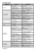
PROBLEM

CAUSE

SOLUTION

Light failure

Switch off or damaged

Turn on the switch

Wire connection is faulty

Check the plug point

The light power supply 

damaged

Replace the light power supply

Light damaged

Replace the light

Too much noise

Unstable placement

Adjust the feet

Loose or damaged screw in 

compressor unit or condenser 

fan

Tighten or replace the screw

5

Содержание WDF157Z

Страница 1: ...INSTALLATION OPERATION AND CARE MANUAL DISPLAY CABINET Imported and distributed by...

Страница 2: ...7Z DCG WDF127Z WDF097Z DCG WDF097Z WDF127F DCG WDF127F WDF097F DCG WDF097F WTF160L DCG WTF160L WTF120L DCG WTF120L 1 INDEX 1 Precautions p 2 2 Transport and handling p 3 3 Installation and operation p...

Страница 3: ...failure service agent authorized by the manufacturer or professional maintenance staff shall be responsible for the maintenance work in case of danger or expanded failure 6 Do not store explosive subs...

Страница 4: ...ng normally Only when the temperature within the cabinet is reduced within the indicated scope can the food be put into the cabinet 5 Don t put too much over hot food in the cabinet to prevent instant...

Страница 5: ...fan does not run Circuit failure Check the terminal bus wiring Fan damaged Repair or replace the fan High cabinet temperature Near a heat source Move the counter or the heat source Frost block Defrost...

Страница 6: ...f 7 Air shield 8 Bottom cover 9 Outlet housing 10 Sliding door 11 Air window 12 Center support 13 Evaporation fan 14 Fan base plate 15 Evaporator 16 Castors 17 Compressor 18 Condenser 19 Control box S...

Страница 7: ...Circuit Diagram WDF series Structure Diagram WTF series 6...

Страница 8: ...compressor and the condenser fan motors The most important is the microcomputer controller It is used to set operating parameters To display target set point In programming mode it selects a parameter...

Страница 9: ...et point value push the key again or wait 10s How to start a manual defrost 1 Push the key for more than 2 seconds and a manual defrost will start In programming mode it browses the parameter codes or...

Страница 10: ...value and move to the following parameter TO EXIT Press or wait 15s without pressing parameter MODEL POWER DIMENSIONS WDF157 Z 0 8kW 240V 1500 x 750 x 1350mm high WDF127 Z 0 7kW 240V 1200 x 750 x 1350...

Страница 11: ...10 This instruction manual is an undivided part of the Display Cabinet Please store in a safe place...

Отзывы: