- 8 -
User Manual
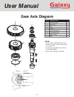
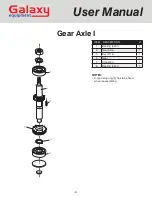
Gear Axle Diagram
NOTES:
• At the center in the shaft unit. To the
above is the gear shaft and gear shaft I.
(see Figure 3-1)
• C-type stop ring (6/8) has to be fixed
when reassembling.
• Be sure that the keys are inserted
ITEM DESCRIPTION
#
1
Bearing (6203)
1
2
Gear Axle
1
3
Key
2
4
Sleeve
1
5
High Speed Gear
1
6
Low Speed Gear
1
7
Bearing 6203
1
8
Plate
1


