background image

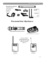
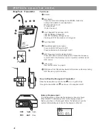
 Handheld 
Transmitter

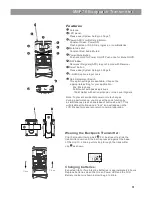
 Bodypack 
Transmitter

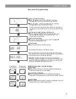
Receiver Programming

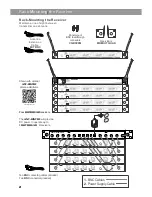
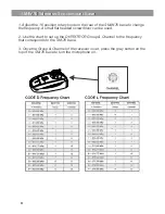
System Setup

System Setup

1

2

3

1

2

3

4

5

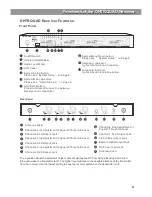
GROUP            CHANNEL

ANTENNA

A                         

B

GROUP

SELECT           

SELECT           

SELECT           

CHANNEL           

CONTROL         

AUTO          

VOLUME          

MANUAL          

CHANNEL           

FREQUENCY

DISPLAY          

MHz

SELECT           LIST           

EXIT           

MASTER        


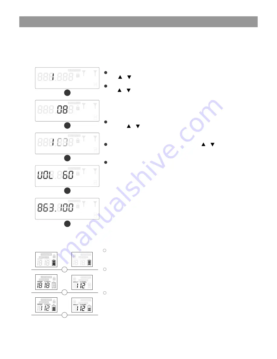
Group and Channel Selection: 

     Press “SET” button twice, “GROUP SELECT” will display, 
      press     or     to choose the appropriate frequency group. 

     Press “SET”again , “

MANUAL CHANNEL SELECT” will display

      press    or     to choose the appropriate channel. 
   
      For best results when operating multiple systems, set all systems to 
      a single group, then set each system to a unique channel within that 
      group.


Auto Frequency Finder function on the Receiver:


   Choose “AUTO CHANNEL SELECT” by pressing “SET” once,

      then press 


or 


.

 Receiver will automatically find a clear   

      frequency with no interference. 


Receiver Volume Setting:

     The receiver has an electronic volume control. Press     or
      from the normal display (00 to 63)


Normal Display:

     Frequency and Antenna A/B (RF Received). 


  Transmitting frequency automatic setup:


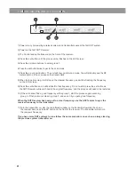
Place the Transmitter “IR” window to face the Receiver “IR” window. 

   Then press the “ASC” button on the desired Receiver. The Transmitter 
   will automatically match the Receiver frequency. 


Attention:

 The distance between the Receiver and Transmitter 

    IR windows should be less than 0.5m during the ASC IR setup. When 
    setting up multiple Transmitters/Receivers, activate the ASC function 
    of only one Transmitter and Receiver at a time.


1

2

3

4

5

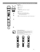
MBP76 Transmitter Status Display  

Battery Status:


Battery Status Indicators for both the Handheld and Bodypack 

    Transmitters feature Four Level Displays.
   

Group and Channel Display:

    After completing the ASC, both the Handheld and Bodypack
    Transmitters will display the Group and Channel numbers selected.  


Normal  Display:

    Both Handheld and Bodypack Transmitters will display Group and
    Channel numbers as well as Battery Status.

1

2

3

7

Содержание Dhtrquad

Страница 1: ...U H F DHTRQUAD MAKERS OF THE ORIGINAL HOT SPOT PERSONAL MONITOR USER S MANUAL WIRELESS MICROPHONE SYSTEM UHF Four Channel Diversity Wireless Receiver DHTRQUAD POWER ANY SPOT IR SYNC...

Страница 2: ...ser Guide and Quick Setting Guide included in your system will provide all the details you need to operate the system efficiently Frequency Band Most countries closely regulate the radio frequencies u...

Страница 3: ...Components System Components O F F O N CHANNEL INFRARED BATT 1 System Components System Components O F F O N CHANNEL INFRARED BATT HH64 HH64SC Handheld Mic Transmitter MBP76 Body Pack Transmitter Vis...

Страница 4: ...annel 1 XLR balanced 8 in 1 Mix XLR balanced 4 in 1 Mix Unbal output H H H H M M M M L L L L SQL SQL SQL SQL Channel 4 XLR balanced Antenna B Antenna B Channel 4 XLR balanced Channel 4 XLR balanced Ch...

Страница 5: ...frequencies 1 2 3 4 5 6 Functions 1 2 3 4 GROUP CHANNEL INFRARED BATT 5 6 BATT GROUP CHANNEL INFRARED Changing Batteries Batteries should be replaced when LCD indicator flashes Unscrew the battery co...

Страница 6: ...eceiver Use in conjunction with Receiver s ASC control LCD screen See system setup on page 8 IR Window Point this window towards IR window on Receiver during ASC frequency synchronization 1 2 3 4 5 6...

Страница 7: ...dicator Constant Red Audio Muted Power Mute Button Push and Hold for Power On Off Push once for Mute On Off IR Window Receives IR signals ASC to synchronize with Receiver Select Button Please see Syst...

Страница 8: ...the SM W76 base to change the frequency A small flat headed screwdriver can be used 2 Use the chart to set up the DHTR TRCR Group Channel to the frequency that corresponds to the SM 76 base 3 Once the...

Страница 9: ...ingle group then set each system to a unique channel within that group Auto Frequency Finder function on the Receiver Choose AUTO CHANNEL SELECT by pressing SET once then press or Receiver will automa...

Страница 10: ...on and it will set itself to that frequency Do not wait to press the set button as the DHT Receiver will revert back to the original frequency and the process will need to be restarted 10 If the unit...

Страница 11: ...ton Press to initiate IR connection between Receiver and Transmitter 10 8 9 Antenna B Indicator Lights when Antenna B is active System Menu Down button Please see System Setup on Page 8 Antenna A Indi...

Страница 12: ...ries in transmitter Distortion or unwanted noise Receiver Indicates RF Remove nearby sources of RF inter ference CD players computers in ear monitor systems etc Distortion level increases gradually So...

Страница 13: ...1kHz tone XLR connector into 600 load 12dBV connector into 3k load 18dBV Output Impedance XLR connector 200 connector 1k XLR output Impedance balanced Pin1 Ground cable shield Pin2 Audio Pin3 No Audio...

Страница 14: ...for AS 1500 MBP76 PS 13 5 35 5 Replacement Power Supply for AS 900 AS 1100 AS 1500 VES VSC ECD ECM PSE TRC DHT AS UA12 14 5 Universal Power Supply for Replacement Power Supply for AS 900 AS 1100 AS 1...

Страница 15: ...ause harmful interference it must operate at a low power level not in excess of 50 milliwatts and it has no protection from interference received from any other device Purchasers should also be aware...

Страница 16: ...io 2013 WARRANTY Information can be viewed online at http www galaxyaudio com warranty php THREE YEAR LIMITED WARRANTY USER S MANUAL DHTRQUAD Specifications in this manual are subject to change withou...

Отзывы: