background image

SMART 200 MP

19 

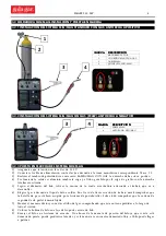
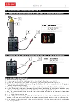
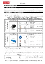
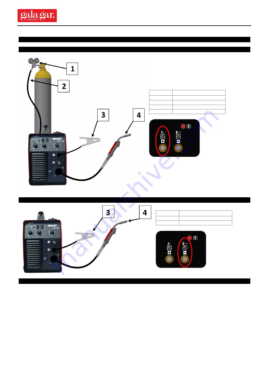
3.2 MIG/MAG WELDING.  INSTALLATION AND START-UP 


3.2.1 INSTALLATION OF STANDARD MIG/MAG SYSTEM WITH GAS.  TORCH TO POSITIVE POLE. 

MARK

MARK

MARK

MARK    

DESCRIPTIO N

DESCRIPTIO N

DESCRIPTIO N

DESCRIPTIO N    

Pressure reducing va lve 

Ma chine-ga s connection 

Ea rth clamp ca ble 

MIG/MAG Torch 

3.2.2 INSTALLATION OF (FCAW) MIG/MAG SYSTEM WITHOUT GAS.  TORCH TO NEGATIVE POLE. 

MARK

MARK

MARK

MARK    

DESCRIPTIO N

DESCRIPTIO N

DESCRIPTIO N

DESCRIPTIO N    

Ea rth clamp ca ble 

MIG/MAG Torch 

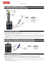
3.2.3.  MIG/MAG SYSTEM START-UP. 

1) Make sure the mains voltage is 230 V.

2) Connect supply cable with the suitable plug to the relevant single-phase tap. See section 2.2.

3) Change the polarity if it is necessary. The torch must be  to positive in MIG/MAG with gas process.

4) If  the  material  to  be   welde d  is  aluminium,  change  the  flexible  cable  and  the  wire  guide   tube   for  the  graphite

cable with the torch totally stretched.

5) Depe nding on the wire diameter, fit the groove of the suitable driving wheel to the work to be  carried out.

6) Choose suitable gas to wire type  to be  welde d. If it has a mobile workstation, check that the gas bottle is securely

held by the bottle-holde r system. Above all check that the safety chain is pe rfectly fastened.

7) Install  the  pressure-reducing  valve  and  connect  gas  hose  checking  that  there  are  no  leakages,  throughout  the

whole circuit.

8) Fit the wire reel into the suppo rt axle.

9) Fit the welding wire into the driving system. Do not force the wire pressure handle, as if this is too tight, the motor

remains on overload and does not reach the maximum spe ed, and if the handle is too slack, the wire could slip.

10) Once the wire has be en fitted, we can then conect the MIG/MAG torch. The wire is loade d into the torch via the

wire purge pushbutton.

Содержание SMART 200 MP

Страница 1: ...LE AUTOMATIQUE DE SOUDAGE MIG MAG Ref 223 00 200MP SMART 200 MP 230V 50 60Hz E ESTE EQUIPO DEBE SER UTILIZADO POR PROFESIONALES EN BENEFICIO DE SU TRABAJO LEA ATENTAMENTE ESTE MANUAL GB THIS EQUIPMENT...

Страница 2: ...NG MODES 16 3 START UP OPERATION AND ADJUSTMENT CONTROLS 17 3 1 OPERATING CONTROLS 17 3 2 MIG MAG WELDING Installation and start up 18 3 3 TIG WELDING Installation and start up 19 3 4 MMA WELDING Inst...

Страница 3: ...r it without any additional charge unless the damage caused to the product is the result of accidents improper use negligence inappropriate accessories unauthorized servicing or modifications to produ...

Страница 4: ...m2 1A V 3 m Con clavija Conexi n m quina gas 2 m racor Cable masa Ruleta 30 0 8 1 0 mm V RECO MENDADO S RECO MENDADO S RECO MENDADO S RECO MENDADO S PARA USO MEDIANTE PRO CESO MIG MAG PARA USO MEDIANT...

Страница 5: ...uientes elementos INSTALACI N DO M STICA CLAVIJA MANGUERA BASE Y PROTECCI N EL CTRICA SCHUKO 2P T 16A BASE 2P 16A TT INTERRUPTOR MAGNETOT RMICO 2P 16A 230V INTERRUPTOR DIFERENCIAL 2P 25A 300 mA INSTAL...

Страница 6: ...EG RESE QUE LA TENSI N DE LA RED COINCIDE CON LA ESTABLECIDA EN LA M QUINA 2 3 MODALIDADES DE USO Existen tres moda lida des pa ra el uso de este equipo SMART 200 MP Carrete di m 200 mm 5 Kg SMART 200...

Страница 7: ...Selector modo pulsaci n 2T 4T H Potenci metro de regulaci n inductancia I Regulaci n Intensidad MMA Regulaci n Tensi n de soldadura MIG MAG J Regulaci n velocidad hilo MIG MAG CAMBIO DE POLARIDAD En i...

Страница 8: ...torcha debe estar a positivo 4 Si el material a solda r es aluminio cambie la sirga y el tubo gu a hilo por la sirga de grafito con la antorcha totalmente estirada 5 Seg n el di metro del hilo colocar...

Страница 9: ...SMART 200 MP 9 10 Una vez encajado el hilo ya puede conectar la antorcha MIG MAG La carga del hilo a la antorcha se realiza mediante el pulsador de sangrado de hilo...

Страница 10: ...fectamente fijada 5 Montar el manorreductor y conectar el tubo del gas comproba ndo que ste no tiene p rdida s a lo largo de todo el circuito 3 4 SOLDADURA DE ELECTRODO REVESTIDO MMA INSTALACI N Y PUE...

Страница 11: ...DEBE FUNCIONAR Q UINA DEBE FUNCIONAR SIEMPRE CON LA SIEMPRE CON LA SIEMPRE CON LA SIEMPRE CON LA ENVOLVENTE P ENVOLVENTE P ENVOLVENTE P ENVOLVENTE PUESTA UESTA UESTA UESTA NO DESCONECTE LA M QUINA SI...

Страница 12: ...azar ventilador El equipo esta situado en un ambiente muy c lido Evite un emplazamiento en donde la exposici n al sol sea directa Existe interiormente una conexi n floja Revisar conexiones el ctricas...

Страница 13: ...ija operativa de fin de arco Evite cebar una longitud final de hilo excesivamente larga LA INTERVENCI N SOBRE EL EQUIPO DEBE SER REALIZADA POR PERSONAL ESPECIALIZADO TANTO AL COMIENZO COMO AL FINAL DE...

Страница 14: ...de solda dura desprendiendo un humo que puede ser muy t xico Esto mismo puede suceder con aquellos materiales que incorporen alg n tipo de tratamiento superficial cincado galvanizado etc Ev tese en to...

Страница 15: ...TANDARD WITH EQ UIPMENT SUPPLIED AS STANDARD WITH EQ UIPMENT DESCRIPTION Instructions Manual SMART 200 MP Input cable 3x4 mm2 1A V 3 m Plug incl Machine gas connection 2 m coupling Earth clamp cable W...

Страница 16: ...CKET 2P 16A TT MAGNETOTHERMAL SWITCH 2P 16A 230V DIFFERENTIAL CIRCUIT BREAKER 2P 25A 300 mA ELECTRICAL SUPPLY INSTALLATION INDUSTRIA L CABLE PLUG SOCKET AND ELECTRICAL PROTECTION DEVICES CETAC 2P T 32...

Страница 17: ...H CONNECTION INTO THE PLUG MAKE SURE THE MAINS VOLTAGE AGREES WITH THAT ESTABLISHED IN THE MACHINE 2 3 USING MODES Three moda lities for the use of this equipment exist SMART 200 MP Reel diam 200 mm 5...

Страница 18: ...pole D Protection Led E ON Led F Selector MMA TIG MIG G Selector mode 2T 4T H Inductance regulation I Intensity regulaci n MMA Voltage regulaci n MIG MAG J Wire Speed regulaci n MIG MAG CHANGE OF POLA...

Страница 19: ...elded is aluminium change the flexible cable and the wire guide tube for the graphite cable with the torch totally stretched 5 Depending on the wire diameter fit the groove of the suitable driving whe...

Страница 20: ...astened 5 Install the pressure reducing valve and connect gas hose checking that there are no leakages throughout the whole circuit 3 4 COATED ELECTRODE WELDING MMA INSTALLATION AND START UP 3 4 1 MMA...

Страница 21: ...PERATED WITH THE HO USING O N THE HO USING O N THE HO USING O N THE HO USING O N DO NOT DISCONNECT THE MACHINE IF IT IS HOT If you have finished the work do not disconnect the machine immediately wait...

Страница 22: ...TCH LD1 O N THERE IS NO SWITCH LD1 O N THERE IS NO REACTIO N WHEN PRESSED REACTIO N WHEN PRESSED REACTIO N WHEN PRESSED REACTIO N WHEN PRESSED Failure of the pistol switch which does not make perfect...

Страница 23: ...not be slowed down when it knocks against the piece The wire length at onset of welding process is too long Correct arc end operation Do not strike too long a final wire length SPECIALIZED PERSONNEL M...

Страница 24: ...rocess giving off fumes which could be very toxic This can also occur with those materials which have some kind of surface coating zinc plated galvanised etc Avoid inhaling the fumes given off in the...

Страница 25: ...el d instructions SMART 200 MP C ble d entr e 3x4mm2 1A V 3 m Sans fiche de raccordement Branchement machine gaz 2 m raccord C ble prise de masse Galet 37 0 8 1 0 mm V RECO MMAND S PO UR PRO C D MIG M...

Страница 26: ...EUR DIFF RENTIEL 2P 25A 300 mA MISE EN APPLICATION INDUSTRIA L FICHE DE RACCORDEMENT SOCLE DE PRISE DE COURANT ET SYST ME DE PROTECTION DU R SEAU LECTRIQUE CETAC 2P T 32A SOCLE DE PRISE DE COURANT 2P...

Страница 27: ...NDE CELLE DE LA MACHINE 2 4 MODALITI S D UTILISATION Trois moda lit s existent pour l utilisation de cette quipement SMART 200 MP Bobine di m 200 mm 5 kg SMART 200 MP avec Poste de travail portable SM...

Страница 28: ...r de mode2T 4T H R glement de l inductance I R glement de l intensit MMA R glement de l tension MIG MAG J R glement de l vitesse du fil MIG MAG CHANGEMENT DE POLARITE Dans l int rieur en ouvrant un co...

Страница 29: ...mat riau souder est en aluminium il faut changer le c ble et le tube guide fil pa r un c ble en graphite et une torche stri e 5 Selon le diam tre du fil poser la rainure de la roue d entra nement ada...

Страница 30: ...ien fix e 5 Monter le d tendeur et brancher le tuyau du gaz en v rifiant s il n y a pa s de fuites tout au long du circuit 3 4 SOUDURE D ELECTRODE REV TU MMA INSTALATION ET MISE EN PLACE 3 4 1 INSTALA...

Страница 31: ...PAS D BRANCHER LA MACHINE SI ELLE EST CHAUDE En fin d utilisation ne pas d brancher imm diatement la machine et attendre que le syst me de r frig ration int rieur la refroidisse compl tement MAINTENIR...

Страница 32: ...t situ dans une ambiance tr s chaude viter un emplacement expos directement au soleil Il y a un branchement int rieur d tach R viser les branchements lectriques de puissance AVEC LA MACHINE EST BRANCH...

Страница 33: ...Corrige l op ration de la fin de l arc vite l amor age d une longueur finale de fil trop longue L INTERVENTION SUR L QUIPEMENT DOIT TRE R ALIS E PAR UN PERSONNEL SP CIALIS AUSSI BIEN AU D BUT QU LA F...

Страница 34: ...car ces derniers peuvent se d composer lors du proc d de souda ge d gageant une fum e qui peut tre tr s toxique Ceci peut galement arriver avec le mat riel qui a re u un traitement zingage galvanisat...

Страница 35: ...KING ELECTRICAL DIAGRAMS PARTS DRAWINGS AND REFERENCE LISTS FORMULA FOR MAKING ORDERS FOR SPARE PARTS Indicate 1 Machine Reference and Serial no 2 Supply Voltage Frequency 3 No of pa rts description a...

Страница 36: ...CONSTRUCTIONS AND ELECTROMECHANICAL CONSTRUCTIONS FABRICATIO N ET VENTE D APPAREILS DE SO UDAGE AUTO G NE LECTRIQ UE ET FABRICATIO N ET VENTE D APPAREILS DE SO UDAGE AUTO G NE LECTRIQ UE ET FABRICATI...

Отзывы: