background image

Pub. 42004-550C 

Elemec3

 Console Manual

—Version 3 

Page 42 of 109


P:\Standard IOMs - Current Release\42004 Instr. Manuals\42004-550C.docx 

07/21 

APLite HUBBCOM Access Panel Creation


1.


Click 

A

DD 

P

ROFILE

 to create a new AP Lite profile PIN. 

A dialog box appears for a description of the AP Lite profile. 

2.


Enter a descriptive name for the profile and click 

C

REATE 

N

EW 

AP


L

ITE 

P

ROFILE

The 

APL

ITE 

P

ROFILE 

B

UILDER

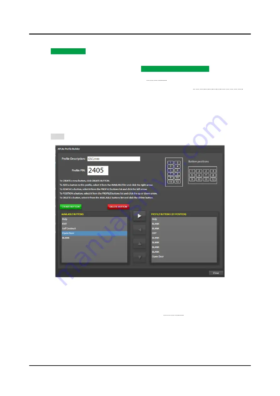
 screen appears (see Figure 44): 

3.


Create the buttons for the access panel if they do not already exist (see the APLite Button Creation 
section). 

4.


Use the left, right, up, and down arrows to assign and order the buttons for the APLite HUBBCOM 
access panel. 

Buttons appear on the APLite HUBBCOM screen in the position they occupy in the list.  Create and 
insert a blank button to place functional buttons in the desired position on the HUBBCOM APLite 
screen. 

5.


Click 

C

LOSE

 to return to the 

APL

ITE 

P

ROFILES

 screen. 


Figure 44.  APLite Profile Builder 

APLite Button Creation


APLite HUBBCOM stations use a static button layout for portrait and landscape displays as shown in the 
upper right corner of the 

APL

ITE 

P

ROFILE 

B

UILDER

 screen (see Figure 44).  Buttons appear on the 

HUBBCOM screen in the position they occupy in the 

P

ROFILE 

B

UTTONS 

(

BY 

P

OSITION

)

 list.  Create and 

insert a blank button in the list to position functional buttons in the desired location on screen.  Use 
created APLite buttons with multiple APLite profiles.  (The figure above shows an APLite profile for a 
landscape display, placing the 

Help

Exit

, and 

Open Door

 buttons at positions one, four, and nine on the 

display). 

Содержание Elemec3 013-02-0095-002

Страница 1: ...ation 7 Manage Configurations 8 LOCAL CONFIGURATIONS Working Directory 8 REMOTE CONFIGURATIONS Parent Directory 9 Create New Configuration 9 Create New Configuration from Template 10 Load an Existing...

Страница 2: ...tup 31 Remove Button 32 Close Button 32 Access Panel Button Configuration 32 Button Properties 33 Create and Modify AP Buttons 33 Reset Buttons 34 Print Preview 34 Close 34 IP Access Panels 35 IP Acce...

Страница 3: ...rty Audio Input Properties 60 Telephone Interface Audio Input Properties 61 VoIP Telephone Interface Setup 62 SIP Properties 63 SIP Registrar Configuration 64 SP2 Properties 65 Auxiliary Inputs 1 5 Au...

Страница 4: ...IONS 86 ADD IP DESTINATION 87 SP2 Integration 87 Configuration Parameter Field Flags 88 Parameter Panes 89 Station Parameter Configuration and Precedence 89 I O States 90 System Properties Screen 91 G...

Страница 5: ...8 Manage Global Mutes 18 Figure 19 Global Audio Mix Setup 19 Figure 20 Amplifiers Summary 20 Figure 21 Add Amplifier 20 Figure 22 Amplifier Properties 21 Figure 23 Amplifier Address Assignment Conflic...

Страница 6: ...67 Page Party Audio Input Properties 60 Figure 68 Telephone Interface Audio Input Properties 61 Figure 69 VoIP Telephone Interface Setup 62 Figure 70 Configure SIP Registrar Properties 63 Figure 71 C...

Страница 7: ...e on the Stations Screen 93 Figure 107 Manage Profiles Screen 94 Figure 108 Profile Selected 94 Figure 109 Global System Settings Pane 95 Figure 110 Page Receive RX Sockets Pane 96 Figure 111 Page Tra...

Страница 8: ...to incorrect programming resulting in a potentially life threatening situation Usage of the E3 Console and E3 Portal applications should be strictly limited to individuals who are factory trained and...

Страница 9: ...iguration to a preset storage location on the host computer called the Elemec bridge Optionally store the configuration file to a custom location using the BROWSE button to select where to save the fi...

Страница 10: ...mplifiers Select the amplifier type Edit the amplifier description Set the channel ID 1 64 Set channel zone display Enable disable load testing Identify if channel is a standby amp Amplifiers on page...

Страница 11: ...Background Music on page 72 7 Import Sound Files for Pre Recorded Messages Action Screen Browse and select an mp3 file Import the mp3 file it into the configuration file Playback Audio Import MP3 on p...

Страница 12: ...mode repeat continuous Select the cancel and acknowledgement options Select the default broadcast zone Select the output and logic flags to activate Select an event chain Event Builder on page 75 For...

Страница 13: ...es Summary screen on page 28 Edit the access panel description Set the access panel address 0 F Enable disable supervision Access Panel Properties screen on page 30 Program the inputs to the I O contr...

Страница 14: ...tions Run the E3 Console Application Start the Elemec3 Console application from the Start Menu Go to Programs GAI Tronics Corporation and click on ElemecConsole3 Optionally double click the desktop sh...

Страница 15: ...remote storage locations to the local working directory to work on them Export a configuration file back to a remote custom storage location or to the Elemec3 bridge folder for upload to an E3 control...

Страница 16: ...lemec3 configuration storage location on the local computer that is common with the E3 Portal application The Elemec bridge is useful when running the E3 Console and E3 Portal applications on the same...

Страница 17: ...nge incrementally with the release of new software Figure 6 Invalid Database Version 3 Click UPGRADE DATABASE to proceed with the configuration version upgrade otherwise click CLOSE Load an Existing C...

Страница 18: ...loaded configuration Choose SAVE CHANGES or DISCARD CHANGES as desired to continue to the CREATE NEW CONFIGURATION screen see the Create New Configuration section Save saves the currently loaded conf...

Страница 19: ...ings System Type Select the system type using the pull down menu Standalone System a system consisting of a single E3 controller with associated amplifiers access panels I O controllers etc A B System...

Страница 20: ...XILIARY AUDIO OUTPUT ONE terminals on the E3 controller See Pub 42004 497 Elemec3 System Controllers for event recorder connection information see the Reference Documentation section Enable audio even...

Страница 21: ...TWORK CONFIGURATION screen see Figure 13 Use this screen to set the network parameters for the E3 controller s Standalone systems only display one system Enter settings for both controllers for an A B...

Страница 22: ...screen to open the MANAGE DEVICE LOCATIONS screen see Figure 14 Locations are text only descriptors associated with any hardware device optional Locations normally specify the physical location of a...

Страница 23: ...n action that may acknowledge or cancel all events or just the current event if possible Select BY PRIORITY to enable the configuration of ack cancel actions that act upon events with equal or lower p...

Страница 24: ...2 Enter a description and click ADD FLAG Description a unique description for the user flag followAudio specifies if the flag asserts only while the event is active and the event s audio is broadcast...

Страница 25: ...h Threshold priority that determines the muting of live speech events The system mutes all live speech events at or below the priority of the selected event The lists shown in the PLAYBACK EVENT MUTIN...

Страница 26: ...n with live speech All events at or above the selected threshold will not attenuate playback events when mixed with listed live speech events Not Mixed lists all live speech and playback events not li...

Страница 27: ...Y screen see Figure 20 The summary screen displays all amplifiers in the system Figure 20 Amplifiers Summary 2 Click ADD AMPLIFIER to add an amplifier 3 Select the appropriate amplifier model on the A...

Страница 28: ...model display below the amplifier graphic The number of channels physically present in the amplifier determines the number of panes displayed onscreen Description generic name for each amplifier chann...

Страница 29: ...nnel configures the current channel to be identical to an existing already configured amplifier channel Click COPY CHANNEL to open the ZONE AUTO ASSIGNMENT dialog box This button is available when the...

Страница 30: ...ial that the amplifier wiring match the hot standby Elemec3 configuration for proper operation The wiring sequence determines the priority for failed amplifiers switching to the hot standby amplifier...

Страница 31: ...o each speaker master audio channel The speaker master powers the speaker remote modules on each channel and transmits power level tap commands and receives speaker coil health check status from the s...

Страница 32: ...onsole 3 Assign AUDIO CHANNELS to the speaker master controller Channel 1 Channel 4 Select the amplifier channel to assign to each of the four audio channels Amplifier channels are assignable to only...

Страница 33: ...EMOTES to add speaker remotes to the Elemec3 system The CREATE SPEAKER REMOTES dialog box displays 3 Select the amplifier channel to assign the speaker remotes to 4 Use the HOW MANY selector to enter...

Страница 34: ...using the drop down list selector The speaker audio output power corresponds to the position of jumper P6 on the speaker remote module and the volume level selected in the E3 Console Table 2 Speaker...

Страница 35: ...eckbox to add access panels connected to the physical API card s installed in the system Access Panel Interface Type Selection There are two types of API cards both types permit connection of up to fo...

Страница 36: ...the button template layout The button template defines the default button layout for the physical access panels in the Elemec3 system see the Access Panel Button Configuration section Add Access Pane...

Страница 37: ...causes the current access panel to swap audio path values with the other panel Audio path assignments of access panels connected to an API type I cards are set by the system Location the physical loca...

Страница 38: ...udspeaker s to prevent acoustic feedback through the access panel s microphone The ACCESS PANEL MUTE SETUP screen is divided into five panes see Figure 34 to configure the settings of the local mute r...

Страница 39: ...ccess panel from the configuration A confirmation prompt displays unless it is disabled by the DON T SHOW THIS AGAIN application option see the Settings section Close Button Click CLOSE to return to t...

Страница 40: ...s type to NOT PRESENT Button Types The following types of access panel push buttons are available Not Present default all unassigned buttons These buttons have a gray top and black bottom Indicator pr...

Страница 41: ...ay period for delayed or staged events Any active events currently delayed immediately activate Select the OVERRIDE ALL or OVERRIDE CURRENT radio button Background Music activate deactivate the backgr...

Страница 42: ...S SUMMARY screen to add IPAP definitions to the Elemec3 configuration Define a maximum of 16 IPAPs in an Elemec3 system Figure 36 IP Access Panels Summary 1 Click ADD IP ACCESS PANEL to add an IPAP IP...

Страница 43: ...but can be acknowledged Urgent fault acknowledgement must occur before clearing the fault Time to Live ttl the maximum number of router hops that the multicast packets traverse before being discarded...

Страница 44: ...ting displays the description of the IPAP being configured Page Level Functions Each button page in the IPAP configuration is a button panel in the IPAP application ADD Button adds button pages to the...

Страница 45: ...ies Use the IPAP BUTTON PROPERTIES pane to configure the buttons on each button page for the current IPAP Figure 40 IPAP Button Properties There are two BUTTON FUNCTIONS at the right end of the IPAP B...

Страница 46: ...t key for the following functionality NEXT PAGE navigate to the next button panel page PREVIOUS PAGE navigate to the previous button panel page HOME navigate to the page defined as home Button Screen...

Страница 47: ...button appearance IPAP panels have two tone colors or are black with a color ribbon Button Type displays the button type Button Color Click and select a color from the palette Button Label sets the la...

Страница 48: ...tion load that profile s button screen Configure multiple HUBBCOM stations with the same profile PIN to load a common screen on multiple HUBBCOM stations GAI Tronics publication 42004 531 covers downl...

Страница 49: ...BBCOM screen in the position they occupy in the list Create and insert a blank button to place functional buttons in the desired position on the HUBBCOM APLite screen 5 Click CLOSE to return to the AP...

Страница 50: ...n Style Select the desired button style color ribbon or solid color from the drop down list Preview view only field displays what the button will look like 3 Click CLOSE to return to the previous scre...

Страница 51: ...the E3 controller and the IP I O devices on the network All IP I O devises communicate on the same control socket The socket number consists of a multicast IP address and port number separated by a c...

Страница 52: ...n I O controller to the system 2 Select one of the seven types of I O controller on the ADD I O CONTROLLER screen see Figure 49 NOTE The IP controller only supports IP I O controllers 3 Click ADD DEVI...

Страница 53: ...s Monitored Relay Module 8 relay outputs with 8 optionally supervised inputs Beacon Monitor 8 supervised outputs with monitoring for power distribution circuits IP Monitored Input Module 8 optionally...

Страница 54: ...42004 550C docx 07 21 Figure 51 Elemec I O Controller Properties Description a generic unique name for the I O controller generated by default Location A the location of the I O controller card see th...

Страница 55: ...er The first input on I O card zero is 0 1 the second input on card zero is 0 2 and so on The properties for each input appear in the columns from left to right across the inputs tab and define the ad...

Страница 56: ...s first so they have addresses 0 1 through 0 8 The output property fields appear from left to right across the outputs tab see Figure 54 and Figure 55 Configure the relay state in column two to enable...

Страница 57: ...t Contact Definitions Inhibit Groups Inhibit groups allow for selectively inhibiting inputs to the Elemec3 system Configure system inputs to trigger an inhibit group that inhibits all inputs in the gr...

Страница 58: ...e descriptive name of the inhibit group Available Inputs Pane Select enabled input contacts on the I O controller cards listed in the AVAILABLE INPUTS pane for addition to the ASSIGNED list The AVAILA...

Страница 59: ...elays the initial transition to active The output remains active for the duration of the on time setting The output remains idle for the duration of the off time setting The output then continuously c...

Страница 60: ...plication consists of a network with multiple servers i e instruments or PLC inputs outputs and one or more clients e g PLC CPU or SCADA system Unique IP addresses identify each client and server The...

Страница 61: ...to configure the Modbus TCP server parameters Modbus TCP modules have two tabs on their property screens INPUTS and OUTPUTS Inputs allow Modbus clients to trigger events in the E3 system Outputs allow...

Страница 62: ...e until an event CANCEL command is issued to the E3 controller Trigger event to trigger when the input coil is ON Auto Inhibit the auto inhibit key switch ignores triggered events when the input coil...

Страница 63: ...output Modbus coil 2 Configure the COIL ADDRESS DESCRIPTION MODE and FOLLOW AUDIO properties for the output 3 Click REMOVE to delete the selected output from the list 4 Click CLOSE to return to the MO...

Страница 64: ...active while the input coil is on and immediately cancels when turned off by a Modbus client Momentary The event is active when the discrete input coil is ON and remains active until an event CANCEL c...

Страница 65: ...ly OFF The output Modbus coil is OFF data 0000 when the event is inactive The output Modbus coil is ON data FF00 when the event is active Follow Audio assuming the event is a playback type the output...

Страница 66: ...rioritized list Sources Enabled The SOURCES ENABLED checkboxes enable the live audio sources in the E3 system 1 Select the check boxes for the audio input sources in the Elemec3 system Each input appe...

Страница 67: ...m on any of the enabled audio input sources see Insert 1 Enabled Insert 2 Enabled Event Choose the event from the dropdown list that will initiate when the controller detects audio on the Page Party i...

Страница 68: ...e Interface the E3 controller uses the VoIP telephone interface instead of an analog PSTN connection for all telephony functions This removes the Ring Count A System property and replaces it with a VO...

Страница 69: ...audio to remove at the end of the playback The STOP TRIM duration is dependent on the operation of the PBX at call termination Ring Count A System number of rings before the telephone interface answer...

Страница 70: ...interval may be different than the value entered Keep Alive Interval time seconds that the E3 controller sends keep alive messages to ensure the port remains open Set this number to zero 0 to disable...

Страница 71: ...egistrar IP PABX Extension extension number assigned to the telephone interface by the SIP Registrar Authentication ID account username assigned by the SIP Registrar Authentication Password account pa...

Страница 72: ...e PARTY MAX DURATION allowing the call to continue if needed The caller hears a beep indicating the party line time limit is about to expire 1 Press the button on the telephone s keypad to extend the...

Страница 73: ...tion maximum duration of an auxiliary input broadcast Start Trim recording delay at the beginning of a record playback event seconds Stop Trim amount of playback audio to remove at the end of the play...

Страница 74: ...address of the multicast input Multicast Port IP port of the multicast input Zones Use the ZONES configuration screen to create and manage communication zones in an Elemec3 system A zone is a set of o...

Страница 75: ...en see the Globals section to enable the option here Beneath the ZONE DESCRIPTION field are four selectable audio outputs Select the audio outputs to include in the zone The available audio outputs ar...

Страница 76: ...button to move selected zones to the ASSIGNED AUDIO DESTINATIONS list on the right IP Destinations add previously defined IP destinations to this zone Select the IP DESTINATIONS from the AVAILABLE DES...

Страница 77: ...docx 07 21 Figure 76 Playback Audio Configuration Playback Audio Configuration Add Message Click ADD MESSAGE on the PLAYBACK AUDIO CONFIGURATION screen to open the CREATE NEW MESSAGE screen Figure 77...

Страница 78: ...ESSAGE to have user logic flag s with the same description as the message automatically added to the created event s Create New Message Click CREATE NEW MESSAGE to finish creating the message Import M...

Страница 79: ...amplifier audio path and load tests The background music resumes when the tests are complete Messages The MESSAGES pane lists the messages for use with the E3 system Messages consist of one or more m...

Страница 80: ...SEQUENCE pane Select a message fragment in the MESSAGE FRAGMENTS list to access the play button Press the green play button to listen to the fragment Message Sequence Change the playback sequence of...

Страница 81: ...created with the AUTOMATICALLY CREATE EVENT option are in the EVENTS AND EVENT GROUPS pane Add Event Click ADD EVENT to open the CREATE NEW EVENT OBJECT screen Enter a description for the event objec...

Страница 82: ...the event type selected see the Event Options section Behavior Playback and External events only event behavior for playback and external audio events Normal attempts to play the specified message imm...

Страница 83: ...parison to the VLC threshold parameter configured on the SP2 station using the VLC AMP MODE operator to perform the comparison EDIT STAGED Click EDIT STAGED to configure the staged portion of an event...

Страница 84: ...S Select each output type as necessary and then select the items in the list to add and click the right pointing arrow button to add them to the ASSIGNED list For each I O card Only the enabled output...

Страница 85: ...e otherwise the event plays only in the available destinations i e play where possible VLC Enabled system broadcasts a VLC Volume Level Control tone to the Page Party output Event Options Use the EVEN...

Страница 86: ...use to source audio for an event via an input contact on an I O card Use this setting whenever an input source doesn t have its own push to talk PTT capability Select the SOURCE from the drop down for...

Страница 87: ...the event Auto cancel the event manually or it will cancel automatically after the Auto Cancel Delay expires Auto Cancel Delay delay seconds for the event to cancel Event Acknowledge Ack Required an a...

Страница 88: ...than a standard event Use event groups to sequence alarms when multiple events are active simultaneously The maximum number of event groups is 16 There are three types of event groups standard sequenc...

Страница 89: ...ent NOTE The E3 controller requires NTP Network Time Protocol service access to implement scheduled events Figure 91 Scheduled Events Select Region Country Select the region or country for the E3 syst...

Страница 90: ...r the period of the event Month s of Year Select EVERY MONTH or the individual months of the year Day s of Week Select EVERY DAY or the individual days of the week Week s of Month Select EVERY WEEK or...

Страница 91: ...access panel status indicators Normal faults automatically acknowledge when the fault clears URGENT access panels status indicators show an Urgent fault Urgent faults are critical system faults that...

Страница 92: ...lable IP AUX INPUTS and IP AUX OUTPUTS These inputs and outputs are part of the system and are not removable Figure 95 System IP Aux IP Inputs Enable the necessary auxiliary IP inputs on the SOURCES E...

Страница 93: ...at the analog MONITOR OUT transmits from the system Figure 96 Edit IP Output Properties Multicast Group IP address for the IP aux output Multicast Port port address for the IP aux output Time to Live...

Страница 94: ...ations to any zone see the Zones section SP2 Integration E3 systems integrate SP2 SVS HUBBCOM devices to add the features and flexibility of these systems The E3 Console implements portions of the SP2...

Страница 95: ...configuration location for that setting in the SP2 configuration The flags display as colored triangular overlays on the upper left corner of each parameter field label and match the color of the loca...

Страница 96: ...TEM PROPERTIES level in the SP2 configuration hierarchy in the E3 Console They appear with slightly dimmed flags to indicate they have default settings Change the value assigned to an attribute at thi...

Страница 97: ...set is off hook ON Always ON OFF Always OFF HEALTHY The station is not detecting any fault conditions FAULTY The station is detecting a fault condition LINKUP The network interface physical link is up...

Страница 98: ...xpands by default see the Global System Settings section Figure 102 System Properties Pane with Global System Settings Pane Expanded Groups Screen Click the GROUPS button at the top of the screen to a...

Страница 99: ...values to attributes at the group and station levels of the hierarchy To assign a profile to a group click the PROFILE field label and select profile one through nine from the dropdown list see the Pr...

Страница 100: ...dress cycle through the SP2 stations that have identifiers in the system This allows browsing to a different station s settings without having to use the station list utility Hostname this station s n...

Страница 101: ...nted in a profile override the previously set value for all parameters assigned in the profile Figure 107 Manage Profiles Screen Select a Profile Click on a profile number to select it Figure 108 Prof...

Страница 102: ...ation file by one whenever making a change to the configuration The SP2 stations use this in conjunction with the CRC of the file to determine whether to use and save these parameters Provisioning Soc...

Страница 103: ...ticast Sockets section Incoming Page Routing The AUDIO OUTPUT fields control the destination of received page audio Select 600OHMOUT SPEAKER or BOTH using the drop down list for each AUDIO OUTPUT Page...

Страница 104: ...in the E3 Console for use in the E3 system Audio Settings Figure 113 Audio Settings Pane Volume Settings Mute Speaker mutes incoming pages during page transmission on any PAGETX socket A E Valid setti...

Страница 105: ...of the 600 ohm audio output for page lines configured for 600 ohm output The value represents the amplitude in millivolts RMS If the Page Destination parameter is set to BOTH then the value stored in...

Страница 106: ...S utility see the VLC Levels section Assign VLC levels to events see the Event Builder section to configure the VLC priority level for the event Assign the VLC levels to SP2 stations on the VLC Settin...

Страница 107: ...rt paging to the PAGETX_B_SOCK multicast address Do not press the handset pressbar to initiate the page Pressing the handset pressbar without holding the ALL CALL button initiates a page on PAGETX_A_S...

Страница 108: ...guration limit the available options All options are available at the remaining configuration levels RTU OUT specifies what activates the RTU output on the station RS IN 1 RS IN 2 specifies the remote...

Страница 109: ...ibit specifies the inhibit groups that affects the SVS inputs see the Inhibit Groups section SVS Volume Settings SVS Amplifier Volume the default volume for SVS stations SVS POE Volume the volume leve...

Страница 110: ...t IP port address of the SNMP service on the SNMP server RTU RS IO See the RTU Settings Excluding SVS section SVS I O Settings See the SVS Settings SVS Only section SP2 Configuration Assets SP2 config...

Страница 111: ...event VLC Levels VLC levels allow setting volume levels independently by event or source Click to create a new VLC level A new VLC level with a default description VLC Level N appears in the VLC PRIO...

Страница 112: ...xists in the configuration a prompt to add the station to the configuration if the station is not found see Figure 120 Click the CREATE STATION button to add the station s ID to the configuration or C...

Страница 113: ...oup selector switch set to the selected group number 0 F Add Stations to Group opens the dialog box at the right to add stations to the configuration in the group selected above STATIONS TO ADD the nu...

Страница 114: ...the configuration to the Elemec Bridge location for upload to an E3 controller using the E3 Portal application Save as Copy saves the current configuration with a new name Save Configuration Changes...

Страница 115: ...vation requests in accord with the configuration Contingent Override A type of event group that automatically substitutes a general event to occur if multiple specific events initiate Elemec3 Portal S...

Страница 116: ...r This type of system has no backup in the case of controller failure System Flag One of several logic outputs without relays originating within the Elemec3 system that provide real time active idle s...

Отзывы: