GAH ITD 130 Скачать руководство пользователя страница 3

3

CONTENTS

CONTENTS

CONTENTS

CONTENTS

CONTENTS

1 INTRODUCTION

1 INTRODUCTION

1 INTRODUCTION

1 INTRODUCTION

1 INTRODUCTION

2 OPERA

2 OPERA

2 OPERA

2 OPERA

2 OPERATOR CONTROLS

TOR CONTROLS

TOR CONTROLS

TOR CONTROLS

TOR CONTROLS

3 TECHNICAL INFORMA

3 TECHNICAL INFORMA

3 TECHNICAL INFORMA

3 TECHNICAL INFORMA

3 TECHNICAL INFORMATION

TION

TION

TION

TION

5 COMMISSIONING

5 COMMISSIONING

5 COMMISSIONING

5 COMMISSIONING

5 COMMISSIONING

7 F

7 F

7 F

7 F

7 FAUL

AUL

AUL

AUL

AULT FINDING

T FINDING

T FINDING

T FINDING

T FINDING

CONTENTS

CONTENTS

CONTENTS

CONTENTS

CONTENTS
Section 1 Intr

Section 1 Intr

Section 1 Intr

Section 1 Intr

Section 1 Introduction

oduction

oduction

oduction

oduction

1-1 Introduction ---------------------------------------------- 2
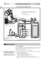
1-2 System Layout ------------------------------------------- 3
1-3 System Requirements ------------------------------------ 4

Section 2 Operator Contr

Section 2 Operator Contr

Section 2 Operator Contr

Section 2 Operator Contr

Section 2 Operator Controls

ols

ols

ols

ols

2-1 Hot  Water Temperature - Heating System ---------------- 7
2-2 Hot Water Temperature - Immersion Heater--------------- 7
2-3 Hot Water Overheating ----------------------------------- 8
2-4 Shut Off Valves ------------------------------------------ 10
2-5 Expansion Relief----------------------------------------- 11
2-6 Servicing ------------------------------------------------ 11
2-7 Protech Anti-corrosion System -------------------------- 11

Section 3 T

Section 3 T

Section 3 T

Section 3 T

Section 3 Technical Information

echnical Information

echnical Information

echnical Information

echnical Information

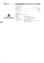
3-1 Specifications ------------------------------------------- 12
3-2 Dimensions --------------------------------------------- 13
3-3 Wiring --------------------------------------------------- 16

Section 4 Installation

Section 4 Installation

Section 4 Installation

Section 4 Installation

Section 4 Installation
4-1 Building Control ----------------------------------------- 18
4-2 Installation ---------------------------------------------- 18
4-3 Expansion Discharge ------------------------------------ 21
4-4 Larger Systems ------------------------------------------ 23
4-5 System Pressure ---------------------------------------- 24
4-6 Parts Supplied - ----------------------------------------- 25

Section 5 Commissioning

Section 5 Commissioning

Section 5 Commissioning

Section 5 Commissioning

Section 5 Commissioning
5-1 Commissioning Checks --------------------------------- 28
5-2 Handing Over ------------------------------------------- 29

Section 6 Servicing

Section 6 Servicing

Section 6 Servicing

Section 6 Servicing

Section 6 Servicing
6-1 Routine Service ----------------------------------------- 30

Section 7 Fault Finding

Section 7 Fault Finding

Section 7 Fault Finding

Section 7 Fault Finding

Section 7 Fault Finding
7-1 Fault Finding -------------------------------------------- 31

6 SERVICING

6 SERVICING

6 SERVICING

6 SERVICING

6 SERVICING

4 INST

4 INST

4 INST

4 INST

4 INSTALLA

ALLA

ALLA

ALLA

ALLATION

TION

TION

TION

TION

IMPORTANT

BEFORE STARTING THE INSTALLATION OF THE DUALSTREAM CHECK ALL COMPONENTS HAVE

BEEN DELIVERED AND ARE IN SATISFACTORY CONDITION.

Содержание ITD 130

Страница 1: ... Installation manual echnical and Installation manual echnical and Installation manual echnical and Installation manual echnical and Installation manual All Models For owners installers and service engineers heating products ...

Страница 2: ...CTRIC All cylinders have electrical supply of 240V enough to endanger life connected to the Immersion Heater Always isolate before adjustment servicing and repair All electrical installation and maintenance of the Dualstream must be carried out by a competent qualified installer All electrical work must be installed to the requirements of these User and Installation Instructions P P P P Patents GB...

Страница 3: ...Relief 11 2 6 Servicing 11 2 7 Protech Anti corrosion System 11 Section 3 T Section 3 T Section 3 T Section 3 T Section 3 Technical Information echnical Information echnical Information echnical Information echnical Information 3 1 Specifications 12 3 2 Dimensions 13 3 3 Wiring 16 Section 4 Installation Section 4 Installation Section 4 Installation Section 4 Installation Section 4 Installation 4 1...

Страница 4: ...sure and flow rate before installing a Dualstream system this will enable the optimum system to be configured to suit conditions Note Direct cylinder heated by immersion heater Indirect cylinder heated by boiler also has immersion heater Dualstr Dualstr Dualstr Dualstr Dualstream is a T eam is a T eam is a T eam is a T eam is a Trademark of GAH HEATING PRODUCTS L rademark of GAH HEATING PRODUCTS L...

Страница 5: ...it the incoming main pressure To maintain maximum mains pressure to the kitchen tap and outside taps it can be fitted following these draw offs when applicable Failure to fit the pressure reducing valve as specified will invalidate warranty A Single Check Valve is supplied if one is not already fitted this should be fitted to the mains supply prior to any connections or take offs to prevent back f...

Страница 6: ...he accumulator water content is up to 65 of its gross volume When sizing the Dualsteam system close consideration should be given to the following 1 Incoming mains supply pipe size 2 Incoming mains flow and static pressure 3 House type building height and number of occupants 4 Typical daily water usage and peak demands 5 Number of bathrooms and total number hot and cold water outlets 6 Types of sh...

Страница 7: ...ty of flow reduction 1 3 4 Frost Protection When planning the installation location of both the accumulator and the unvented cylinder consideration must be given to the risk of frost and the use of frost protection The design of the accumulator gives it a degree of frost protection enabling it to be located within the dwelling loft space or garage without further protection The cylinder can also b...

Страница 8: ... SYSTEM THERMAL CUT OUT SAFETY THERMOSTAT 2 2 1 Hot Water Control 125 150 210 300 Cylinders When the hot water is heated by the electric Immersion Heater the temperature of the hot water at the taps is controlled by the Immersion Heater Thermostat This is located under the black Immersion Heater cover The temperature range is 30 C to 85 C Recommended setting is 60 C Fig 2 2a shows the approximate ...

Страница 9: ...and Immersion Heater and contact your installer 2 3 2 Water Heated by Immersion Heater When the hot water is heated by the Immersion Heater its integral Thermal Cut Out Thermostat prevents the water within the cylinder overheating The Immersion Heater Thermal Cut Out Thermostat is a manual reset type this means it has a small button that pops up when the thermostat has been tripped by overheating ...

Страница 10: ...ET S If the Immersion Heater Thermal Cut Out Thermostat trips more than once switch off the Immersion Heater and contact your installer To reset 125 150 210 300 Cylinders Isolate the Immersion Heater Remove the Immersion Heater cover and using a small screwdriver press the Bipolar Safety reset button see fig 2 3b To reset 500 Cylinder Isolate the Immersion Heater Remove the Immersion Heater cover ...

Страница 11: ...ains water supply to the dwelling 2 4 2 Single Check Valve If fitted Normally located after the Stop Cock Prevents water back feeding to main Shuts off the mains water supply to the dwelling 2 4 3 Cold Water Shut Off Valve Normally located in the cold feed close to the accumulator Shuts off the cold water to the taps 2 4 4 Supply Water Shut Off Valve Normally located where the cold supply connects...

Страница 12: ... Restriction in hot water pipework iii Loss of air pressure in the accumulator resulting in no expansion 5 Contact the installer before restarting the system Fig 2 5a Tundish Note At least the Tundish or discharge pipe should remain in view do not box in or cover up either It is recommended the system is inspected by an approved engineer once per year The service procedure is included in section 6...

Страница 13: ... 6 8 1 8 3 2 2 6 2 8 3 2 e t a R w o l F y r a m i r P h 3 m 9 0 9 0 9 0 9 0 9 0 h 3 m 9 0 e t a r w o l F g n i t a R r e g n a h c x E t a e H W k 8 2 7 1 6 4 7 1 0 4 2 9 5 4 2 1 6 2 8 1 3 0 0 2 0 0 2 0 0 2 a e r A e c a f r u S l i o C m 7 6 0 8 7 0 9 8 0 9 8 0 9 8 0 5 1 5 7 0 5 7 0 5 7 0 h 3 m 9 0 e t a r w o l F g n i t a R r e g n a h c x E t a e H r a l o S W K 0 7 2 0 7 2 0 7 2 r e w o l a...

Страница 14: ...S 7291 Kite marked WRAS approved Soldered copper fittings EN 1254 1 BS864 Part 2 WRAS approved Compression type fittings EN 1254 2 WRAS approved Push fit fittings BS7291 pt1 pt2 WRAS approved must be specified as suitable for sealed systems IMPORTANT Plastic pipe and fittings should not be used within 1m of the cylinder TECHNICAL INFORMA TECHNICAL INFORMA TECHNICAL INFORMA TECHNICAL INFORMA TECHNI...

Страница 15: ...e c a p s y t p m E t h g i e W 0 0 1 0 0 1 s e r t i l 5 5 o t p u m m 0 1 4 m m 0 9 8 m m 0 9 9 g k 3 6 1 0 0 2 0 7 1 s e r t i l 0 9 o t p u m m 5 3 5 m m 0 4 9 m m 0 4 0 1 g k 4 0 3 0 4 2 0 4 2 s e r t i l 0 3 1 o t p u m m 5 3 5 m m 5 1 2 1 m m 5 1 3 1 g k 2 7 3 0 0 3 0 1 3 s e r t i l 0 6 1 o t p u m m 5 3 5 m m 0 0 5 1 m m 0 0 6 1 g k 5 4 4 0 0 5 0 5 4 s e r t i l 0 4 2 o t p u m m 8 6 6 m ...

Страница 16: ...0 5 5 Ø 9 4 2 2 4 4 6 9 8 g k 0 3 g k 6 7 1 5 1 2 I D T l 5 9 0 2 m 9 8 0 W k 0 0 4 2 8 0 5 1 0 5 5 Ø 9 4 2 2 1 5 5 9 2 1 g k 3 4 g k 2 5 2 5 5 2 I D T l 3 3 5 2 m 9 8 0 W k 9 5 4 2 0 7 7 1 0 5 5 Ø 9 4 2 2 1 5 3 6 5 1 g k 9 4 g k 3 0 3 5 0 3 I D T l 4 6 9 2 m 9 8 0 W k 0 1 6 2 2 5 0 2 0 5 5 Ø 9 4 2 2 1 5 9 3 8 1 g k 5 6 g k 2 6 3 0 0 5 I D T l 5 9 4 m 5 1 W k 8 1 3 0 7 8 1 4 1 7 Ø 0 3 2 0 0 7 g k ...

Страница 17: ... W k 0 0 2 g k 0 6 g k 5 1 3 5 0 3 I S T I s e r t i l 5 0 3 m 1 1 W k 0 7 2 m 5 7 0 W k 0 0 2 g k 6 6 g k 0 7 3 3 2 3 Indirect Twin Cylinder Dimensions COMPRESSION FITTINGS ARE SUPPLIED TO ADAPT THE CYLINDER TAPPINGS TO THE PIPE SIZES SHOWN Fig 3 2c Twin Cylinder Dimensions r e d n i l y C l e d o M S N O I S N E M I D A B Ø C D E F G 5 1 2 I S T I 5 8 4 1 8 7 5 Ø 0 8 5 3 4 8 0 6 2 1 3 1 2 1 8 4 ...

Страница 18: ...stant Cables as shown B1 A1 B2 A2 B3 A3 1 3 4 6 2 5 THERMOSTAT With Thermal Safety Device HEATING ELEMENTS BOTH PHIALS ARE INSERTED IN THIS HOLE L1 L2 L3 N1 N2 N3 EARTH TERMINAL 3 x 2 5mm 20A 3 CORE HEAT RESISTANT CABLE L1 L2 L3 green yellow blue brown L1 L2 L3 6 4 2 5 3 1 N L 3 x 2kW HEATING ELEMENTS 3 x 2 5mm 20A 3 CORE HEAT RESISTANT CABLE 45 AMP DOUBLE POLE SWITCH THERMOSTAT With Thermal Safet...

Страница 19: ...ed for hot water heated light SWITCHED LIVE from BOILER HEATING CONTROLS blue green yellow orange brown orange NOT USED or BOILER or PUMP depending on system grey HONEYWELL V4043H Normally Closed FLOW FROM BOILER NEUTRAL EARTH HIGH LIMIT THERMOSTAT Normally Closed CYLINDER THERMOSTAT Normally Closed 3 3 2 Immersion Heater 125 150 210 and 300 Cylinders Fig 3 3b Immersion Heater Wiring Diagram 125 1...

Страница 20: ...ly with any r All electrical work must comply with any r All electrical work must comply with any relevant r elevant r elevant r elevant r elevant regulations that apply at the time of egulations that apply at the time of egulations that apply at the time of egulations that apply at the time of egulations that apply at the time of the installation the installation the installation the installation...

Страница 21: ...00 Fig 4 2c Combination Valve Cylinders 500 4 2 4 Expansion Vessel An expansion vessel is supplied with the GAH Dualstream system The expansion vessel should be fitted to the combination valve a BSP port is provided for this The expansion vessel must always be open to the system with NO shut off or isolation valves in the connection pipe 3 5Bar PRESSURE REDUCING VALVE 3 5Bar PRESSURE REDUCING VALV...

Страница 22: ...commend and promote the use of scale prevention devices and water softeners in areas that are known to have hard water Installed correctly they prolong the life of equipment and help prevent lime scale formation in the pipework Water Softeners provide the advantages of soft water as well as preventing scale build up on taps and shower heads Water softeners and any mains fed system must be of adequ...

Страница 23: ...cceptance are 1 Ideally below a fixed grating and above the water seal in a trapped gully 2 Downward discharges at a low level i e up to 100mm above external surfaces such as car parks hard standings grassed areas etc These are acceptable providing that where children may play or otherwise come into contact with discharges a wire cage or similar guard is positioned to prevent contact whilst mainta...

Страница 24: ... 2 2 m m 8 2 m m 5 3 m m 2 4 m 9 o t p u m 8 1 o t p u m 7 2 o t p u m 0 1 m 4 1 m 7 1 1 G m m 8 2 m m 5 3 m m 2 4 m m 4 5 m 9 o t p u m 8 1 o t p u m 7 2 o t p u m 4 1 m 7 1 m 3 2 4 3 5 Worked Example G temperature and pressure relief valve TPRV with a discharge pipe D2 having four elbows and length of 7m from the tundish to the point of discharge From Table 1 Maximum resistance allowed for a str...

Страница 25: ...consult GAH HEATING PRODUCTS LIMITED e information consult GAH HEATING PRODUCTS LIMITED e information consult GAH HEATING PRODUCTS LIMITED e information consult GAH HEATING PRODUCTS LIMITED Fig 4 4a Typical Multi System Layout FOR REFERENCE ONLY WATER SOFTENER HTPV ACCUMULATOR 1 INCOMING MAINS SUPPLY ACCUMULATOR 2 HTPV BALANCED COLD SUPPLY TO TAPS HOT SUPPLY TO TAPS CYLINDER 1 CYLINDER 2 EXPANSION...

Страница 26: ...arge pressure is factory set at 2 Bar 7 The recommended accumulator charge pressure is 1 5 Bar below the mains pressure with an absolute minimum of 0 5 0 8 Bar consult GAH Heating Products for further information Also refer to 5 1 1 8 The Combination Valve has a Pressure Relief Valve PRV set at 6 Bar 8 The unvented cylinder has a Temperature and Pressure Relief Valve PRV set at 6 Bar ACCUMULATOR C...

Страница 27: ... u s s e r P e v l a V 1 n i a m g n i m o c n i r o F 0 1 t i K l e s s e V n o i s n a p x E 1 n o i s n a p x E r e d n i l y C r o F m e t I t r a P y t Q s e t o N 1 r e d n i l y C 1 d e b m u l p e r P r e t a e H n o i s r e m m I w c 2 t e e F r e d n i l y C 3 r e d n i l y C o t d e t t i f d e i l p p u S 3 r o t a l u m u c c A 1 n o i s s e r p m o c m m 8 2 d e b m u l p e r P 4 e v...

Страница 28: ...s Boiler Flow 22mm Indirect only 22 x M I Coupler supplied Fit Motorised Valve supplied Boiler Return 22mm Indirect only 22 x M I Coupler supplied 4 6 3 Connections to Dualstream 125 150 210 and 300 Cylinders DOMESTIC HOT WATER 22mm FROM MAINS 22mm DHW SECONDARY DOMESTIC HOT WATER PLUGGED TUNDISH DISCHARGE BOILER FLOW 22mm COLD INTO CYLINDER TO ACCUMULATOR 22mm ACCUMULATOR COMBINATION VALVE HTPV V...

Страница 29: ...o be arranged and sized to comply with Building Regulations Boiler Flow 28mm Indirect only 28 x M I Coupler supplied Fit Motorised Valve supplied Boiler Return 28mm Indirect only 28 x M I Coupler supplied DOMESTIC HOT WATER 28mm FROM MAINS 28mm SECONDARY DOMESTIC HOT WATER PLUGGED TUNDISH DISCHARGE BOILER FLOW 28mm COLD INTO CYLINDER TO ACCUMULATOR 28mm ACCUMULATOR COMBINATION VALVE TPRV VALVE CYL...

Страница 30: ...s 11 Turn on Mains Stop Cock and allow the system to fill 12 Open all domestic taps in turn to purge air 13 Check system for leaks including around the Immersion Heater 14 Check the installation of the tundish complies with the Building Regulations 15 Check no water is discharging from the Pressure Relief Valve or the TPR valve this will be evident at the Tundish 16 Test the operation of the TPR V...

Страница 31: ...nd the air charge of the Accumulator When the incoming mains pressure is less than 3 5 Bar the pressure differential will be higher than 1 5 Bar and the Accumulator will not fill sufficiently therefore it may be necessary to lower the Accumulator air charge pressure The procedure for changing the Accumulator pressure is given below this can be done before the system has been filled It may be done ...

Страница 32: ... the pressure of the accumulator this should be 1 5 Bar below the mains pressure with an absolute minimum of 0 5 0 8 Bar 16 Remove Immersion Heater remove limescale and examine the element In hard water areas it is probably better to replace the Immersion Heater if heavily scaled Refit Immersion Heater with gasket 17 Most glass lined cylinders will have at least one magnesium anode remove and insp...

Страница 33: ...stream cylinder or accumulator TURN OFF ELECTRIC SUPPLY then turn off the mains water supply to the house via the stop cock Make allowance to store some cold water for necessities Open both cold and hot taps to drain the cylinders of water thus preventing any further leaks and consult your installer 1 Check to ensure combination valve filter is not blocked 2 Check all isolation valves are fully op...

Страница 34: ...34 Notes ...

Страница 35: ...35 Notes ...

Страница 36: ...36 ...

Страница 37: ...37 GAH Heating Products Ltd Building 846 Bentwaters Parks Rendlesham Woodbridge Suffolk IP12 2TW www gah co uk Tel 01394 421160 Fax 01394 421170 email mail gah co uk heating products ...

Отзывы: