Gage Bilt GB731SHV5/LB68 Скачать руководство пользователя страница 16

16


GB731SHV5/LB68 INSTALLATION TOOL: SERIAL # 1001 & ABOVE


CONTACT GAGE BILT FOR ALL OTHER SERIAL NUMBERS.


2/19 REV. 1/23


REMOVING ACTUATOR ASSEMBLY

-

AIR (704130) 


1.


Remove actuator lever assembly (704343) and pin

-

slotted (400608) from the 

handle

-

split (700326). 


2.


Insert a 

5/8” 

open end / adjustable wrench around actuator assembly

-

air (704130).


3.


Loosen the actuator assembly

-

air (704130).


4.


Remove wrench. Unthread and remove the actuator assembly

-

air (704130) 


with fingers from the handle

-

split (700326). 


INSTALLING ACTUATOR ASSEMBLY

-

AIR (704130) 


1.


Apply Teflon® tape onto threads of actuator assembly

-

air (704130) one to two wraps.


2.


Thread the actuator assembly

-

air (704130) all the way into handle

-

split (700326) with 

fingers.


3.


Insert and turn 

5/8” 

open end / adjustable wrench and snug tight approximately 1/4 

-

 1/2 turn.


4.


Reattach actuator lever assembly (704343) and pin

-

slotted (400608) to the handle


split (700326). 


ACTUATOR ASSEMBLY

-

AIR


WARNING

Disconnect tool from its power source before actuator removal or installation. Severe personal injury may occur if 


power source is not disconnected.


CAUTION:  

Actuator assembly

-

air (704130) can break if not careful.


CAUTION:  

Do not over tighten actuator assembly

-

air (704130). Snug tighten only.
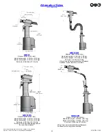
 

OVERHAUL


NOSE ASSEMBLY / DISASSEMBLY


To disassemble nose assembly from tool, take the following steps:


1.  Disconnect air supply to tool.


 2.


 Loosen and removed fitting

-

regulator (703627) then pull out insert 


 (731355) from rear of cap

-

vacuum (731418).


 3.


 Loosen and remove retaining nut (211102), retaining nut stop (240102), 


 and anvil holder assembly.


 4.


 Attach wrench to flats on collet and insert 

1/4” 

Allen wrench (comes 


 with tool) into hex in rear of piston (731211) and remove remaining 


 nose assembly parts (IE* collet, extension

-

collet & jaws). (Individual 


 parts vary depending on nose assembly).


 5.


 Assembly is the opposite of disassembly. Follow steps in reverse to 


 assemble your nose assembly. (See also nose assembly data sheet).


* See overhaul and parts lists on pgs. 16 

-

 19 for more assembly or 


  disassembly information.


     * Insert (731355) must be removed (before assembly/disassembly of noses) 


  to install Allen wrench into rear of piston.


Images may not reflect actual tool.


*Use 731355 insert with 

3/16” 

and 5mm only.


 DO NOT use with 

1/4” 

or 6mm


To assemble nose assembly to tool, take the following steps:


1.  Hand thread and tighten assembled collet (with jaw) and extension

-

collet to piston on tool. (Individual parts vary depending on 


 nose assembly). See proper data sheet for more information.


2.


 With insert (731355) removed, insert 

1/4” 

Allen wrench (comes with tool) into hex in rear of piston (731211) and Attach wrench to 


 flats on collet and tighten assembly to piston on tool. See proper data sheet for more information.


 3.


 Slide anvil assembly over collet then slide retaining nut stop and retaining nut over anvil assembly and thread and tighten retaining nut to tool. 


 (Note: Retaining nut stop fits into ears on anvil. See proper data sheet for more information).


 4.


 With 

1/4” 

Allen wrench removed from rear of piston and end cap on tool, place insert (731355) into rear of cap

-

vacuum until flush.


 (NOTE: Insert (731355) is only used on 

3/16” 

and 5mm

” 

nose assemblies. DO NOT use with 

1/4” 

or 6mm nose assemblies).


 5.


 Attach and tighten the fitting

-

regulator (703627) with pintail evacuation tube to the cap

-

vacuum (731418).


* See overhaul and parts lists on pgs. 16 

-

 19 for more assembly or disassembly information.


     * Insert (731355) must be removed (before assembly/disassembly of noses) to install Allen wrench into rear of piston.


  (NOTE: Insert (731355) is only used on 

3/16” 

and 5mm

” 

nose assemblies. DO NOT use with 

1/4” 

or 6mm nose assemblies).


Содержание GB731SHV5/LB68

Страница 1: ...AVAILABLE WORLDWIDE E MAIL US FOR A DISTRIBUTOR NEAR YOU 44766 Centre Court Clinton Twp MI 48038 USA Ph 1 586 226 1500 Fax 1 586 226 1505 solutions1 gagebilt com www gagebilt com GAGE BILT MADE in US...

Страница 2: ...ion of Functions 5 Warnings 6 Principle of Operation 7 How to set up the GB731SHV5 LB68 8 How to use the GB731SHV5 LB68 9 Maintenance and Hydraulic Thread Preparation 10 Filling 11 Bleeding 12 Stroke...

Страница 3: ...r or subsequent user in repairing or replacing defective goods or if the goods covered by this warranty are reworked or subjected to any type of additional processing This warranty is void if Seller i...

Страница 4: ...B731SHV5 LB68 installation tool operates on 90 to 100 psi 6 2 6 9 bar of air pressure providing the maximum efficiency At 90 psi 6 2 bar of air pressure the GB731SHV5 LB68 does not exceed 81 5 dB A an...

Страница 5: ...23 DESCRIPTION OF FUNCTIONS Actuator Handle Assembly Head Cylinder Assembly Fitting Regulator Air Inlet Actuator Lever Assembly Air Line Hydraulic RETURN Hose Hydraulic PULL Hose Handle Split Hanger...

Страница 6: ...el 5 Select maintain and replace the consumable inserted tool as recommended in the instruction handbook to prevent an unnecessary increase in noise 6 If the power tool has a silencer always ensure th...

Страница 7: ...downward direction The air below the air piston assembly is then directed through the valve sleeve and exhausted out of the bottom of the tool Simultaneously the piston rod assembly connected to the a...

Страница 8: ...erator MUST read and understand all warnings and cautions WARNING It is required that eye protection hearing protection and safety boots be worn at all times while handling this equipment WARNING The...

Страница 9: ...ing protection and safety boots be worn at all times while handling this equipment WARNING The users or the user s employer must assess specific risks that could be present as a result after each use...

Страница 10: ...and nose assembly for damage Replace Repair if necessary See Overhaul pgs 15 19 for tool repair Inspect hoses and couplings for wear damage and leaks Replace Repair if necessary See hydraulic thread...

Страница 11: ...over both hydraulic hoses A 1668 and air line 704344 8 Push piston 731211 in head cylinder assembly 731199 to rear until you achieve 785 19 9 mm see B on pg 12 from full forward position Stretch enti...

Страница 12: ...95 4 52 Nm Do not over tighten 9 Connect air supply cycle tool ten times 10 Check stroke of 600 15 24 mm using instructions a thru c and diagrams below We recommend using dial calipers a With the actu...

Страница 13: ...on chart to select stroke limiter 4 Remove button head cap screw 402482 and stat o seal S572 from front bleeder hole 5 Install cap vacuum 731418 and torque to 45 foot lbs 61Nm Oil will drain from fron...

Страница 14: ...embly 704262 is recommended b Check o rings on valve sleeve 703139 valve spool assembly 703142 and valve plug 704145 If worn or damaged re place Valve sleeve removal tool assembly 704163 is recommende...

Страница 15: ...late Gage Bilt part no 402723 or other lubricant is recommended during reassembly to prevent tearing or distorting of o rings The disassembly and re assembly procedure can be accomplished by utilizing...

Страница 16: ...arts IE collet extension collet jaws Individual parts vary depending on nose assembly 5 Assembly is the opposite of disassembly Follow steps in reverse to assemble your nose assembly See also nose ass...

Страница 17: ...y 722132 6 After removal of air piston assembly 704121 slide piston rod assembly 731333 back up to the end of its travel Using packing plug wrench assembly 704150 remove packing plug 704118 7 With pac...

Страница 18: ...18 GB731SHV5 LB68 INSTALLATION TOOL SERIAL 1001 ABOVE CONTACT GAGE BILT FOR ALL OTHER SERIAL NUMBERS 2 19 REV 1 23 PARTS LIST...

Страница 19: ...19 GB731SHV5 LB68 INSTALLATION TOOL SERIAL 1001 ABOVE CONTACT GAGE BILT FOR ALL OTHER SERIAL NUMBERS 2 19 REV 1 23 PARTS LIST...

Страница 20: ...04D 30OS NAS06 2480 45 NAS06 204C 34OS 1 4 1 NAS08 352 102 NAS08 2480 202 NAS08 204C 25OS NAS08 204D 30OS NAS08 2480 452 NAS08 204C 34OS 5 MM MGP5 730B 10 MGP5 2480 20 MGP5 204C 25OS MGP5 204D 30OS MG...

Страница 21: ...ioxide and unidentified organic compounds will be evolved when this material undergoes combustion ACCIDENTAL RELEASE MEASURES Protective Measures Eliminate all sources of ignition in vicinity of spill...

Страница 22: ...600 15 24 mm Hand held weight 5 75 lbs 2 61 kg Entire tool weight 5 75 lbs 2 61 kg Pull load 4 800 lbs 21 35 kN Alternative Styles Sold Separately GB731SH Stroke 600 15 24 mm Hand held weight 2 25 lbs...

Страница 23: ...23 GB731SHV5 LB68 INSTALLATION TOOL SERIAL 1001 ABOVE CONTACT GAGE BILT FOR ALL OTHER SERIAL NUMBERS 2 19 REV 1 23 This page intentionally left blank...

Страница 24: ...C TITE IS A REGISTERED TRADEMARK LA CO INDUSTRIES TEFLON IS REGISTERED TRADEMARK OF E I DUPONT DE NEMOURS CO CHERRY MAX CHERRYLOCK ARE REGISTERED TRADEMARKS OF CHERRY AEROSPACE Many kits available inc...

Отзывы: