Gage Bilt GB585 Скачать руководство пользователя страница 8

REV. 12/17 


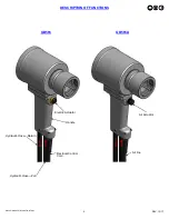
GB585 / GB585A INTALLATION TOOL


HOW TO SET-UP THE GB585 / GB585A 

WARNING:  

Only qualified and trained operators should install, adjust or use the assembly power tool for non-threaded  


  mechanical fasteners.  


WARNING:  

Operator 

MUST 

read and understand all warnings and cautions. 


WARNING:  

It is required that eye protection, hearing protection and safety boots be worn at all times while handling this 

equipment. 


WARNING:  

The users or the user’s employer should assess specific risks that could be present before each use based on  


their application.  


 ●  Be sure there is adequate clearance for tool and operator's hands before proceeding. Keep fingers clear of 


     any moving parts. Keep fingers clear from fasteners and installed materials. Severe personal injury may result.


 ●  

Verify the air lines and/or hydraulic hoses are not a trip hazard.


 ●  

Ensure that there are no electrical cables, gas pipes, etc., which can cause a hazard if damaged by the tool

.


●  

Verify that hydraulic hose fittings and couplings, air and electrical connections are secure before each use.


WARNING: 


Do not pull rivet in the air. Personal injury from fastener ejecting may occur.


WARNING: 


Do not carry from hoses or use as a hammer.


WARNING:  

Do not use in explosive atmosphere.


WARNING: 


Ensure air hose is securely connected to avoid possible hose whipping.


WARNING: 


Always disconnect air supply, where applicable, when tool is not in use to prevent accidental start-up.


WARNING:


Do not exceed the maximum relief-valve setting stated on the tool and manual. 


WARNING: 


Do not operate when recommended pressures are exceeded as it could cause severe personal injury and or  


damage the equipment. 


WARNING: 


Use only Gage Bilt hydraulic hoses and couplings, or equivalent, rated for 10,000 psi. (689.5 bar) working pressure. 


CAUTION: 


Do not use beyond the design intent. 

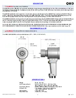
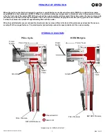
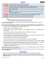
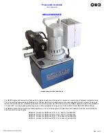
1. Set hydraulic power unit to the recommended pressure, 5,700 psi (393.0 bar) Max. for the pull and 2,400 psi (165.5 bar) Max. for the 
  return. Gage Bilt pressure gage assy (942280) (sold separately) is recommended to aid in this procedure. “See hydraulic power unit  
  manual for correct procedure when adjusting pressures”.  


Note: 

Power units require a free flow of air for cooling purposes and should therefore be positioned in a well ventilated area 


free from hazardous fumes. 


2. Turn off the hydraulic power unit. Wipe all couplers clean before connecting. Failure to do so can result in damage to the couplers 
 

and cause overheating. Connect hydraulic hoses then electric cord to power supply. 


3.  Turn hydraulic power unit on and cycle tool five times by depressing actuator to ensure piston is in the full forward position. 


4.  Disconnect electric cord / air line from power supply.  


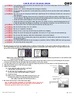
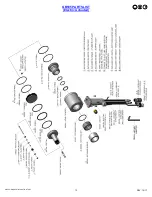
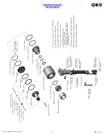
5.  Attach nose assembly 


5a.  Screw collet assembly onto piston until top of 


collet flat lines up with top of tool. 


5b.  If collet lock is not in piston groove, continue to turn 


1/4 turn clockwise until ball lock engages in groove. 


5c.  Tighten set screw. 


5d.  Slide anvil over assembled collet. While pushing down on anvil, 


install split ring, sleeve and retaining ring (furnished with tool). 


(See proper data sheet for further instructions.) 


6. Re-connect electric cord / air line into power supply.  


Note: See GB7624 NOSE ASSEMBLY ATTACHMENT video as reference for 


proper nose assembly attachment procedure located on our website, at : 


http://www.gagebilt.com/rivet_tools_videos.php


5,700 psi  

(393.0 

bar)  

Max.  

2,400 psi  

(165.5 

bar)  

Max.  

Содержание GB585

Страница 1: ...DWIDE E MAIL US FOR DISTRIBUTOR NEAR YOU GB585 GB585A INSTALLATION TOOL ORIGINAL INSTRUCTIONS 44766 Centre Court Clinton Twp MI 48038 USA Ph 1 586 226 1500 Fax 1 586 226 1505 solutions gagebilt com www gagebilt com GAGE BILT MADE in USA ...

Страница 2: ... 4 Description of Functions 5 Safety Warnings 6 Principle of Operation 7 How to set up the GB585 GB585A 8 How to use the GB585 GB585A 9 Maintenance and Hydraulic Thread Preparation 10 Troubleshooting 11 Overhaul 12 Parts Lists GB585 13 Parts Lists GB585A 14 Nose Assembly Selection Chart and Accessories 15 Powerunits Accessories 16 20 ...

Страница 3: ...ubsequent user in repairing or replacing defective goods or if the goods covered by this warranty are reworked or subjected to any type of additional processing This warranty is void if Seller is not notified in writing of any rejections or defects within 1 year after the receipt of the material by the customer THIS WARRANTY IS MADE IN LIEU OF ALL OTHER WARRANTIES EXPRESSED OR IMPLIED INCLUDING ME...

Страница 4: ...unit set at 5 400 5 700 psi 372 3 393 0 bar maximum PULL pressure and 2 200 2 400 psi 151 7 165 5 bar maximum RETURN pressure The tool comes equipped with 2 feet 61 m of hydraulic hoses and couplings electric switch and cord The GB585A installation tool operates on hydraulic pressure developed by the GB910 GB912 Powerunits set at 5 400 5 700 psi 372 3 393 0 bar maximum PULL pressure and 2 200 2 40...

Страница 5: ...5 REV 12 17 GB585 GB585A INTALLATION TOOL DESCRIPTION OF FUNCTIONS GB585 GB585A Electric Actuator Handle Electrical Control Cord Hydraulic Hose Return Hydraulic Hose Pull Air line Air Actuator ...

Страница 6: ...and secure footing 5 Release the start and stop device in the case of interruption of energy supply 6 Use only lubricants recommended by the manufacturer 7 Avoid unsuitable postures as it is likely for these positions not to allow counteracting of normal or unexpected movement of the tool 8 If the tool is fixed to a suspension device make sure that fixation is secure 9 Beware of the risk of crushi...

Страница 7: ... is forced forward swaging the collar into locking grooves of the fastener Further force breaks the pintail off approximately flush with the collar When the switch actuator assy is released the directional valve reverses oil flow to the back of the piston assy and pushes the nose as sembly off of the swaged fastener The pintail ejector hydraulically pushes the spent pintail out of the nose assembl...

Страница 8: ...e severe personal injury and or damage the equipment WARNING Use only Gage Bilt hydraulic hoses and couplings or equivalent rated for 10 000 psi 689 5 bar working pressure CAUTION Do not use beyond the design intent 1 Set hydraulic power unit to the recommended pressure 5 700 psi 393 0 bar Max for the pull and 2 400 psi 165 5 bar Max for the return Gage Bilt pressure gage assy 942280 sold separate...

Страница 9: ... tool Verify that hydraulic hose fittings and couplings air and electrical connections are secure before each use WARNING Do not pull rivet in the air Personal injury from fastener ejecting may occur WARNING Do not carry from hoses or use as a hammer WARNING Do not use in explosive atmosphere WARNING Ensure air hose is securely connected to avoid possible hose whipping WARNING Always disconnect ai...

Страница 10: ...hten Replace or Repair if necessary See hydraulic thread preparation below Cycle the tool several times to assure there are no leaks during use Only use a hydraulic power source equipped with relief valves and pressures set within specific limits See required max pressure for pull and return Keep hydraulic system free of dirt Avoid letting couplers contact a dirty floor Do not use as a hammer to f...

Страница 11: ...e powerunit instruction manual b Restrictions in either hydraulic lines hoses or couplings Check and tighten clean or replace See hydraulic thread preparation pg 10 5 OIL LEAKAGE a Hydraulic oil leaks from connections Tighten threaded connections Do not use Teflon tape See hydraulic thread preparation pg 10 b Oil leaks from tool Determine source of leak and replace worn or defective o rings and ba...

Страница 12: ...ead compound such as Slic tite Gage Bilt part no 403237 DO NOT USE TEFLON TAPE See hydraulic thread preparation pg 10 Apply hot glue to wire connections of the actuator assy 480137 to ensure wires DO NOT contact each other or handle assy Electric actuated riveter GB585 only TOOL DISPOSAL 1 When tool life is met drain hydraulic oil from tool and dispose of the hydraulic oil in accordance with SDS d...

Страница 13: ...13 REV 12 17 GB585 GB585A INTALLATION TOOL GB585 PARTS LIST Electric Actuated ...

Страница 14: ...14 REV 12 17 GB585 GB585A INTALLATION TOOL G585A PARTS LIST Air Actuated ...

Страница 15: ...N B The second set of digits represent ONE of the tool models which MAY be used with this head Model 585 C The last set of numerical digits signify the Gun Line or reach of the pulling head to the nearest tenth of an inch 41 is 4 1 inch Gun Line FASTENER LOCKBOLT HIGH TENSILE PULL TYPE C50L NOSE ASSEMBLY KEY A The first set of numerical digits represent the diameter of the fastener in 32nds of an ...

Страница 16: ... The GB940 Hydraulic Powerunit is available in 115 volt or 230 volt single phase alternating current Output pressures as shipped are PULL 5400 5700 psi RETURN 2200 2400 psi The GB940 Hydraulic Powerunit is available separately or in kits including hydraulic quick disconnect couplers electrical connectors and hose cord kits in various lengths GB940 12 includes the GB940 and 12 ft 3 7 m Hose Kit par...

Страница 17: ... a two position air hydraulic pump four way control valve and relief valve mounted on the reservoir The GB910 Hydraulic Powerunit is available separately or in kits including hydraulic quick disconnect couplers air connectors air lines and hydraulic hoses in various lengths GB910 12 includes the GB910 and 12 ft 3 7 m Hose Kit Air part 910701 GB910 26 includes the GB910 and 26 ft 7 9 m Hose Kit Air...

Страница 18: ...btained through a higher 12 cubic inches a minute output pump Quick disconnect hydraulic couplings and air control socket are included to attach the equipment hydraulic hoses and air control tube The GB912 Hydraulic Powerunit is available separately or in kits including hydraulic quick disconnect couplers air connectors air lines and hydraulic hoses in various lengths GB912 12 includes the GB912 P...

Страница 19: ...19 REV 12 17 GB585 GB585A INTALLATION TOOL This page intentionally left blank ...

Страница 20: ...GISTERED TRADEMARK OF FISKE BROTHERS REFINING CO SLIC TITE IS A REGISTERED TRADEMARK OF LA CO INDUSTRIES INC LOCTITE IS A REGISTERED TRADEMARK OF HENKEL CORPORATION This page intentionally left blank Riveter Kits Available Sold Separately Gage Bilt offers a wide selection of standard and custom kits tailored to your needs ...

Отзывы: