


12
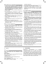
4. Start-up and use
–
Check for correspondence between the compressor plate
data with the actual specifications of the electrical system. A
variation of ± 10% with respect of the rated value is allowed.
–
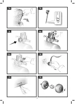
Insert the plug of the power cable in a suitable socket (
pic. 6
)
checking that the button of the pressure switch located on the
compressor is in the OFF «O» position.
–
Check the oil level by means of the oil dipstick (
pictures 7a-
7b
), and if necessary top up.
–
At this point, the compressor is ready for use.
–
Operating on the switch of the pressure switch (
pic. 1
), the
compressor starts, pumping air into the receiver through the
delivery pipe.
–
When the upper calibration value (set by the manufacturer)
has been reached, the compressor stops, venting the excess
air present in the head and in the delivery pipe through a valve
located under the pressure switch.
This facilitates subsequent restart due to the absence of
pressure in the head. When air is used, the compressor restarts
automatically when the lower calibration value is reached (2
bar between upper and lower).
–
The pressure in the receiver can be checked on the gauge
provided (
pic. 8
).
–
The compressor continues to operate according to this automatic
cycle until the switch of the pressure switch is turned.
–
Always wait at least 10 seconds from when the compressor
has been switched off before restarting this.
–
All compressors are fitted with a pressure reducer. Operating
on the knob with the tap open (turning it in a clockwise direction
to increase the pressure and in a counterclockwise direction
to reduce this,
pic. 9a
), air pressure can be regulated so as
to optimize use of pneumatic tools. After setting the value
required, the ring-nut underneath must be tightened to fasten
the knob (
pic. 9b
).
–
The value set can be checked on the gauge.
–
Please check that the air consumption and the maximum
working pressure of the pneumatic tool to be used are
compatible with the pressure set on the pressure regulator
and with the amount of air supplied by the compressor.
–
Always pull out the plug and drain the receiver once you have
completed your work (
pictures 10-11
).
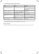
5. Cleaning and maintenance
Warning!
Pull the power plug before doing any cleaning and mainte-
nance work on the appliance (pic. 10).
Warning!
Wait until the compressor has completely cooled down.
Risk of burns!
Warning!
Always depressurize the tank before carrying out any
cleaning and maintenance work (pic. 11).
Cleaning
Never clean the machine and its components with solvents,
flammable or toxic liquids. Us only a damp cloth making sure
you have unplugged the compressor from the current outlet.
Maintenance
–
BEFORE CARRYING OUT ANY OPERATION, ALWAYS
PULL OUT THE PLUG AND DRAIN THE RECEIVER
COMPLETELY (pictures 10-11).
–
Check that all screws (in particular those of the head of the unit)
are tightly drawn up (torque 10 Nm = 1.02 Kgm).
The control must be performed before the first start-up of the
compressor and subsequently before the first intensive use in
order to restore the correct closing torque value modified as a
result of heat expansion.
–
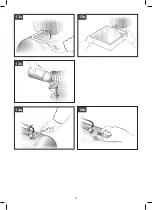
After loosening any safety screws, clean the intake filter
according to the type of working environment and at least every
100 hours (
picture 12
). If necessary, replace the filter element
(clogging of the filter reduces compressor performance and an
inefficient filter causes increased wear).
–
Replace the oil after the first 100 hours of operation and every
300 hours subsequently (
pictures 13a-13b-13c
). Remember
to check the oil level at regular intervals.
Use
SAE 40
. (For cold climates,
SAE 20
is recommended).
Never mix different grade oils. If the oil changes color (whitish
= presence of water; dark = overheated), it is good practice to
replace the oil immediately.
–
Periodically (or after working with the compressor for more
than an hour), drain the condensate that forms inside the
receiver (
pic. 11
) due to the humidity in the air. This protects
the receiver from corrosion and does not restrict its capacity.
–
Spent oil and condensate MUST BE DISPOSED OF in
accordance with environmental protection regulations and
current legislation.
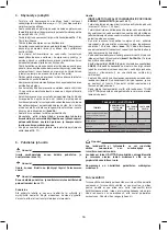
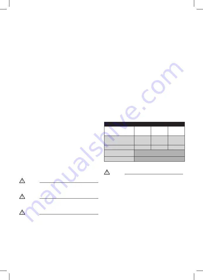
TABLE 1 – MAINTENANCE
FUNCTION
AFTER THE
FIRST 100
HOURS
EVERY 100
HOURS
EVERY 300
HOURS
Cleaning of intake filter and/
or substitution of filtering
element
•
Change of oil
•
•
Tightening of head tension
rods
At start-up and after the first hour of work
Draining tank condensate
Periodically and at the end of work
Warning!
If the water that condenses is not drained, it may corrode
the receiver, reducing its capacity and impairing safety.
As it is a contaminating product, condensate must be DIS-
POSED of in accordance with laws on protection of the en-
vironment and current legislation.
The compressor must be disposed in conformity with the
methods provided for by local regulations.
Safety valve
The safety valve has been set for the highest permitted pressure
of the pressure vessel. It is prohibited to adjust the safety valve
or remove its seal. Actuate the safety valve from time to time to
ensure that it works when required. Pull the ring with sufficient
force until you can hear the compressed air being released.
Then release the ring again.
Содержание 501755411
Страница 7: ...7 3a 4 1 ON 2 OFF 3b a c b e d 6 5b 5a...
Страница 8: ...8 7b 7a 8 9a 9b 10 11 12...
Страница 9: ...9 14a 13a 13b 13c 14b...
Страница 26: ...26 KIT FXA FC24 1 8 KW 1 4 m 20 dB...
Страница 27: ...27 5 C 40 C 4 5 1 5 2 S3 25 2 5 7 5 1 2 2 3 a b c d e 4...
Страница 29: ...29 5 14a 14b 1 100 100 300...
Страница 42: ...42...
Страница 43: ...43...