5
Cable Installation
Receiver Cable - Route the receiver cable from the RD15 to
where the receiver is mounted. Turn the receiver power off prior
to connecting the receiver cable. Connect the 7-socket connector
to the receiver. Connect the 6-pin connector to the RD15.
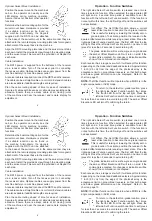
Optional Power Cable, Battery - Plug the 3.5 mm barrel
connector into the remote display power jack identified by the
lightning bolt ( ). Route the power cable with terminal ends to
the machine battery. Connect the red wire to the battery's positive
(+) terminal and the black wire to the negative (-) terminal. The
RD15 will operate off machine power ranging from 10 VDC to
30 VDC. Reverse voltage and over voltage protection are built in.
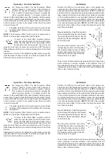
Optional Power Cable, Coiled Outlet Adapter - Select the 3.5
mm barrel connector. The positive (+) side aligns with the "TIP"
side. Plug the connector into the remote display power jack ( ).
Plug the adapter into an appropriate power outlet. The maximum
extended length of the coil cable is 8 feet (2.4 m).
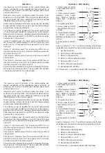
Earphone Jack
An earphone jack is provided for audio output and is identified
by an earphone symbol (
). User provided earphones with a
standard 2.5 mm barrel connector can be used. It is recommended
to use earphones that have a volume control adjustment. Fast
audible signal is receiver too high. Constant signal is receiver
on-grade. Slow audible signal is receiver too low.
8
Operation - LED Display
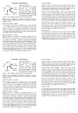
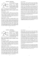
Deadband Indication
The 5 light blade tilt indication
functions as a deadband
(accuracy) indicator. Pressing
the right side select function
switch will temporarily activate
a tilt display LED to show the
current accuracy selection of the
receiver. The deadband indication LED will always blink.
Note:
If a set-up deadband is included in the receiver, the set-
up and the fine deadband will both be indicated by the Fine
Deadband LED.
Blade Tilt Indication - MCR2+
If the MCR2+ has Version 5 software and the tilt indication
is on, the RD15 LED's will mimic the receiver tilt display and
provide 5 channels of tilt indication. If the MCR2+ receiver has
Version 4 software, the tilt display will always be on and shown
in the fine tilt accuracy. Refer to the receiver operating manual
for specific blade tilt indicator settings.
Blade Tilt Indication - MCR3
Although there is no provision for displaying blade tilt on the
MCR3 receiver itself, the function can be activated if the receiver
has Version 5 software. Activation requires simultaneously
pressing the power switch, plumb switch, and deadband switch of
the receiver. When successfully activated, the receiver's outside
green on-grade LED's will blink, the center green LED will be on
and the RD15 tilt display will become active. Repeat the three
button procedure to turn the display off. The receiver's outside
green on-grade LED's will blink and the center green LED will be
off. The blade t
ilt deadba
nd is fine, or ± 0.5°. If the MCR3 receiver
has Version 4 software, the tilt display will always be on.
Fine
Deadband
Standard
Deadband
Wide
Deadband

