


WARNING
1.5V AAA x3
1000A
OFF
LoZ V
Hz%
V
Hz%
V
600A
AUTO POWER OFF
AC/DC
TRUE RMS
REL
MODE
RANGE
PEAK
HOLD
1
2
10
9
11
8
12
13
14
3
4
5
6
7
A
B
C
D
E
F
G
H
I
J
K
L
M
N
O
P
Q
1000A
OFF
LoZ V
Hz%
V
Hz%
V
600A
AUTO POWER OFF
AC/DC
TRUE RMS
û
1000A
OFF
LoZ V
Hz%
V
Hz%
V
600A
AUTO POWER OFF
AC/DC
TRUE RMS
ü
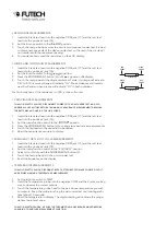
DESCRIPTION
1. Current clamp
2. Non-contact AC Voltage Indicator Lamp
3. Clamp trigger
4. Relative / Backlight Button
5. LCD Diplay
6. MODE / INRUSH select button
7. RANGE button
8. PEAK/VFD button
9. Rotary Function Switch
10. Data Hold / Flashlight button
11. Battery cover
12. Flashlight
13. COM Input jack
14. V Ω Hz% CAP TEMP jack
A. Low Impedance input mode
B. DC (Direct Current)
C. Minus Sign
D. AC (Alternating Current)
E. Low battery
F. Inrush Current mode
G. Auto Power Off
H. Auto Range Mode
I. Diode test mode
J. Audible Continuity
K. Peak Voltage value
L. Relative mode
M. Data hold mode
N. Variable Frequency Drive Voltage Value
O. Units of Measure List
P. Frequency/Duty Cycle Test Mode
Q. 6000 Count (0-5999) Measurement Reading
OPERATING
Read and understand all warning and precautions statements listed in the safety-
section of this manual prior to using this meter. Set the function select switch to the
OFF position when the meter is not in use.
AC/DC CURRENT MEASUREMENTS
Ensure that the test leads are disconnected from the meter before making current
clamps measurements.
1. Set the Function switch to the 1000A AC/DC or 600A AC/DC range
2. If the range of the measured is not known, select the higher range first, than
move to the lower range if necessary.
3. Press the trigger to open the clamp. Fully enclose one conductor to be meas-
ured.
4. The clamp meter LCD display will show the reading.
AC/DC VOLTAGE MEASUREMENT
1. Insert the blank test lead into the negative COM jack [13] and the red test
lead into the positice V jack [14].
2. Set the function switch to the ACV or DCV position
3. Connect the test leads in parallel to the circuit under test
4. Read the voltage measurement on the LCD display


