background image

35 


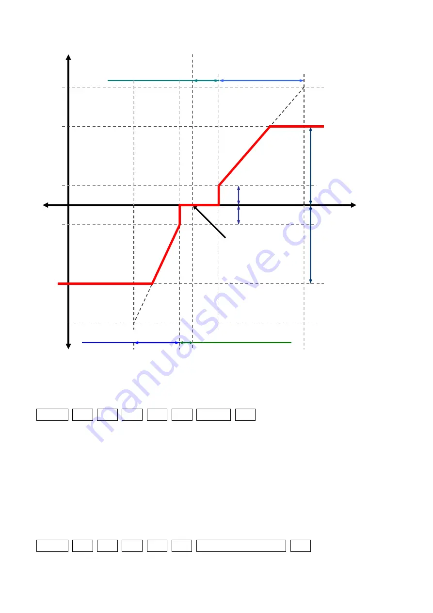
Fig. 4.1 

The relationship of Output Torque, Angle and Compliance settings


Ex.1) Set Punch of the servo (ID: 1) to 1[%]( = 100(0064H)). 

Hdr          ID          Flg        Adr        Len      Cnt            Dat          Sum 

  FA AF      01      00      1C      02      01      64 00      7A 


Ex.2) Set the servo (ID: 1) as shown below; 


CW Compliance Margin   

=   

    03H 


CCW Compliance Margin    =   

    03H 


CW Compliance Slope 

=   

    14H 


CCW Compliance Slope 

=   

    14H 

        Punch 


0064H


Hdr          ID          Flg        Adr        Len      Cnt                            Dat                          Sum 

  FA AF      01      00      18      06      01      03 03 14 14 64 00      7A 


Output Torque 

CCW 

CW 

CCW 

CW 

Present Angle 

Goal position 

【Punch】 

【Punch】 

【CW Compliance Slope】 

【CCW Compliance Slope】 

【CCW Compliance Margin】 

【CW Compliance Margin】 

Maximum Torque 

Maximum torque 

Maximum Torque 
×【Max Torque(%)】


Maximum Torque 
×【Max Torque(%)】 

Содержание RS204MD

Страница 1: ...1 1M23Z06502 User s Manual Ver 1 04 RS204MD Command Type Servo for Robot Instruction Manual Caution Read this instruction manual before use Keep this manual handy for immediate reference For models...

Страница 2: ...ce position 8 PART NAMES HANDLING INSTRUCTIONS 9 HOW TO ATTACH THE SERVO 10 PIN ASSIGNMENT OF THE CONNECTOR 11 COMMUNICATION SETTINGS 11 DEFINITION OF ANGLE AND ITS RANGE 14 Definition of 0 degrees an...

Страница 3: ...Read Write for PWM 33 No 24 No 25 Compliance Margin 1 Byte Hex Read Write 34 No 26 No 27 Compliance Slope 1 Byte Hex Read Write 34 No 28 No 29 Punch 2 Byte Hex Read Write 34 4 3 Variable RAM Area 36...

Страница 4: ...and Free Horn for RS20x RS30x 48 OPTION PARTS 49 HOW TO USE BRACKET 51 Fixing Brackets to RS204MD 51 Jointing Other Parts Servos 51 Usage of Brackets 52 Dimensions with Brackets 52 DIMENSIONS OF TERMI...

Страница 5: ...al injury or property damage if the warning is ignored Symbols Prohibited Mandatory Cautions for Use Caution Do not disassemble or alter the servo Otherwise it may cause breakage in the gear box fire...

Страница 6: ...due to a strong external force it may cause smoke fire or damage Cautions for Storage Caution Do not store the servos in the following conditions Places where the temperature is over 60 or below 20 P...

Страница 7: ...refer to p 50 Optional parts for optional parts and repair parts 1 Servo RS204MD x1 2 Servo Horn x1 3 Screw to fix servo horn x1 M2x8 Tapping Screw Servo Horn and Screw are attached to the servo 4 Cab...

Страница 8: ...ia TTL communication Compliance Control With this feature the movement of the RS204MD is controlled in accordance with the distance between the present and target positions This enables the robot to m...

Страница 9: ...crews be careful not to get dust or foreign matter inside the case Route the cable through the free horn hole in the bottom case when using the Inward Connector Bending cables strongly will cause disc...

Страница 10: ...e Fig 2 2 Screw Depth Fig 2 3 Reference for the length of the screw to fix other parts Other Parts Plate t 1 0mm Hole to fix cases and other parts Screw Depth up to 7mm from each Reference Surface 1 8...

Страница 11: ...e cable b Connectors of the servo Fig 2 4 Connector Pin Assignment Communication Settings Set your Communication parameters as follows Baud Rate 115 2 kbps 9 6 kbps 230 4 kbps refer p 30 Data bit leng...

Страница 12: ...ly excessive force to the board Also when unplugging grasp the cable and pull it out slowly Fig 2 5 Installing unplugging the connector Installing the connector Push the connector from upside unpluggi...

Страница 13: ...nward Connector Fig 2 6 Routing the cable Caution Use Phillips 1 screwdriver Do NOT overtighten the screws Do NOT pinch the cables Do NOT damage the circuit board Remove the screws and Bottom Case Ins...

Страница 14: ...nsor When in this range Present Position p 39 will be 555 5 and Torque Enable p 38 will be 00H Torque OFF To turn on the torque again please move output axis to Operational Range then send Torque ON c...

Страница 15: ...ype Servo with USB RS485 Converter RSC U485 etc Power Hub TB RV71EH 7 4V 3W is required somewhere in the system The maximum number of RS204MD to be connected as TTL Command Type Servos is 24 When thes...

Страница 16: ...Systems as PWM Type Servo Fig 3 2 Systems with PWM Type servo Please note that the servos made by Futaba Corporation may malfunction depending on the specification of the controller used for PWM serv...

Страница 17: ...of Disabled Connection 1 RS485 Command Type Servos do not work if they are connected via the Hub for 3 Wire Servo When both RS485 Command Type Servos and TTL Command Type Servos are used in the same...

Страница 18: ...Fig 3 4 TTL Command Type Servo Example of Disabled Connection 2 The servos may malfunction if more than one Hub with Power Switch for TTL Command Type Servo RV71EH 7 4V 3W is connected in the same sys...

Страница 19: ...x communication The signal line can be switched alternately for transmission or reception of data Normally RS204MD stand by in a receiving mode When they receive commands to get the data of or the sta...

Страница 20: ...C U485 etc While the servos are operated as PWM Type Servo rewriting the parameters cannot be executed Therefore the servos are operated with the prewritten parameters Servo ID You can set ID numbers...

Страница 21: ...urn Packet or write ROM Area and so on For details refer subsequent pages Address Set the starting address of Memory Map to be changed Length Length is the length of the data Set the number of bytes o...

Страница 22: ...ags 40H and sending a packet of address FFH Length 00H Count 00H to a servo data of the memory map from No 4 to No 29 is written in Flash ROM ex Write Flash ROM of the servo ID 01 Hdr ID Flg Adr Len C...

Страница 23: ...nt after finishing Write Flash ROM Bit 4 Initialize the memory map from No 4 to No 29 Setting this bit to 1 Flags 10H and sending a packet with Address FFH Length 00H Count 00H and data FFH to a servo...

Страница 24: ...29 1 0 0 1 Return the data of memory map No 42 No 59 1 0 1 1 Return the data of memory map No 30 No 41 1 1 1 1 Return the specified number of bytes of data starting from the specified address 2 Direc...

Страница 25: ...Set 0 for Long Packet always Address Set the starting address of Memory Map to be changed Length Length is the length of the data for each servo Length the number of bytes of the data for each servo 1...

Страница 26: ...e to 10 degrees to the Servos ID 1 and ID 2 and 50 degrees to the servo ID 5 Hdr ID Flg Adr Len Cnt VID Dat VID Dat VID Dat Sum FA AF 00 00 1E 03 03 01 64 00 02 64 00 05 F4 01 ED The check sum of the...

Страница 27: ...he servo Table 4 4 Flags of Return Packet Bit Value Meanings 7 0 Normal 1 Error Temperature Limit Torque OFF 6 0 Reserved 5 0 Normal 1 Error Temperature Alarm 4 0 Reserved 3 0 Normal 1 Error Write Fla...

Страница 28: ...umber H 20H No 2 Firmware Version 1Byte Hex Read It is the version of the servo s firmware Its value is depending on the version at production 0x03 in the example below Firmware Version 03H Saving 2 B...

Страница 29: ...e Limit L RW 11 0BH FAH CCW Angle Limit H RW 12 0CH Reserved 13 0DH Reserved 14 0EH 37H Temperature Limit L R 15 0FH 00H Temperature Limit H R 16 10H Reserved 17 11H Reserved 18 12H Reserved 19 13H Re...

Страница 30: ...alue can be changed ONLY when the Torque is OFF Torque Enable is 00H It is the direction of rotation of the servo Its initial value is 00H that means the normal rotation and the value of 01H means rev...

Страница 31: ...Write Flash ROM packet and Reboot Servo packet must be sent No 7 Return Delay 1Byte Hex Read Write This value can be changed ONLY when the Torque is OFF Torque Enable is 00H It is the delay time for...

Страница 32: ...2 01 E8 03 E1 Ex 2 Set the CCW Angle Limit of servo ID 1 to 100 0 degrees 100 0 degrees 1000 FC18H CCW Angle Limit L 18H CCW Angle Limit H FCH Hdr ID Flg Adr Len Cnt Dat Sum FA AF 01 00 0A 02 01 18 FC...

Страница 33: ...the condition is shown as below Table 4 8 Torque Conditions Value Condition 0 00H Torque OFF 1 01H Torque ON and keep the same angle 2 02H Brake mode refer p 38 The servo continues to maintain the an...

Страница 34: ...o increases in proportion to the error between the present angle and aim angle The flexibility of the servo increases in proportion to this value No 26 is for CW and No 27 is for CCW The unit is 1 0 d...

Страница 35: ...w CW Compliance Margin 03H CCW Compliance Margin 03H CW Compliance Slope 14H CCW Compliance Slope 14H Punch 0064H Hdr ID Flg Adr Len Cnt Dat Sum FA AF 01 00 18 06 01 03 03 14 14 64 00 7A Output Torque...

Страница 36: ...fficient RW 39 27H Reserved 40 28H Reserved 41 29H Reserved 42 2AH 00H Present Position L R 43 2BH 00H Present Position H R 44 2CH 00H Present Time L R 45 2DH 00H Present Time H R 46 2EH 00H Present S...

Страница 37: ...rvo ID 1 to 90 0 degrees Hdr ID Flg Adr Len Cnt Dat Sum FA AF 01 00 1E 02 01 84 03 9B Ex 2 Move servo ID 1 to 90 0 degrees Hdr ID Flg Adr Len Cnt Dat Sum FA AF 01 00 1E 02 01 7C FC 9C No 32 No 33 Goal...

Страница 38: ...ondition is shown as below Value Condition 0 00H Disable Torque OFF 1 01H Enable Torque ON 2 02H Brake mode The initial value is 0 00H when the power is turned on In Brake mode the servo does not have...

Страница 39: ...39 FA AF 01 00 24 01 01 02 27...

Страница 40: ...its range is 1600 1600 When the output axis is in Dead zone the value will be 15B3H 555 5degrees Ex Get Present Position of the servo ID 1 To get the value of Present Position No 42 and No 43 of the...

Страница 41: ...acket with Memory Map No 42 No 49 is the same as the previous paragraph A Short Packet to require Return Packet with Memory Map No 42 No 49 is Hdr ID Flg Adr Len Cnt Sum FA AF 01 09 00 00 01 09 An exa...

Страница 42: ...to require Return Packet with Memory Map No 42 No 49 is Hdr ID Flg Adr Len Cnt Sum FA AF 01 09 00 00 01 09 An example of Return Packet is An example of Return Packet is Data Hdr ID Flg Adr Len Cnt 42...

Страница 43: ...quire Return Packet with Memory Map No 42 No 49 is Hdr ID Flg Adr Len Cnt Sum FA AF 01 09 00 00 01 09 An example of Return Packet is A Short Packet to require Return Packet with Memory Map No 42 No 49...

Страница 44: ...accept Torque ON command until it is rebooted or is turned off and on the power again When Present Temperature reaches Temperature Limits temperature around the motor of the servo reaches to 120 140...

Страница 45: ...A Short Packet to require Return Packet with Memory Map from No 42 and No 59 is Hdr ID Flg Adr Len Cnt Sum FA AF 01 09 00 00 01 09 An example of Return Packet is Data Hdr ID Flg Adr Len Cnt 42 43 52...

Страница 46: ...mand Type 144 degree PWM Type CCW 150 degree Command Type 144 degree PWM Type Supply Voltage 3 7 6 0 V Temperature Range to operate 0 40 degrees Celsius to store 20 60 degrees Celsius Power Source DC3...

Страница 47: ...47 Dimensions RS204MD Fig 5 1 RS204MD without Servo Horn mm...

Страница 48: ...vo Horn and Free Horn mm A gap of 0 3mm occurs between Servo Horn and the body of servo when the Servo Horn is attached exactly Free Horn is not fixed to the servo It turns freely around the axis of t...

Страница 49: ...49 Servo Horn and Free Horn for RS20x RS30x Fig 5 3 L Servo Horn R Free Horn...

Страница 50: ...minal Box with 4 EH Connectors BB0132 TB22PP Terminal Box with 4 Servo Connectors Cables BB1182 SERVO CABLE AD RC B 150 To convert ADH connector to Servo Connector 150 BB1183 SERVO CABLE AD RC B 300 T...

Страница 51: ...BS3470 CASE SET RS204MD Cases Upper Middle Bottom BS3469 GEAR SET RS204MD Gears gears shafts Ball bearings BS3477 GREASE MULTIPURPOSE Grease for servos 8g Appropriate amount 0 05g for RS204MD Horns B...

Страница 52: ...ed to fix RS204MD to other parts easily Fixing Brackets to RS204MD Fig 5 7 RS204MD with Brackets Jointing Other Parts Servos Fig 5 8 Jointing RS204MD Tapping Screw 1 2x5 Tapping Screw 1 2 3 5 Tapping...

Страница 53: ...53 Usage of Brackets Fig 5 9 RS204MD with Brackets Dimensions with Brackets Fig 5 10 RS204MD with Brackets mm...

Страница 54: ...54 Dimensions of Terminal Board Use tape to fix TB 41AD Fig 5 11 Dimensions of TB 41AD mm...

Страница 55: ...55 FUTABA CORPORATION 2019 May...

Отзывы: