TECDIS Installation Manual
Page 37
3.2.1 Inputs
Note: All position inputs to TECDIS from all external sensors must be in WGS-
84 format
.
In the first area (“Inputs”), you can configure the message type and source of the different
possible sensor inputs.
In the first column, “Select sensor” you can select which sensor you want to configure.
The
sensor name will turn green when valid NMEA sentences of the type specified is received on
the specified port.
In the box next to “Sentence” you can select the type of NMEA sentence this input should be
read from on a drop down menu. For more information about the different NMEA sentences, see
the table below.
In the third box, (“Port”) you can select the COM port the selected sensor data type should be
read from by using the two arrow buttons at the bottom of the column (to the right of the drop
down menu for speed/port).
The COM port field will turn red if the specified COM port is
already in use by monitor, alarm control or RCU-018. This means that the port selection is
invalid, and that another COM port must be selected either for the sensor or the conflicting
equipment.
In the fourth column, “Sensor Description”, you can manually enter a text description that
identifies the source instrument of the sensor data.
NB: When there is a port collision (when there is an attempt to use the same port for multiple
conflicting functions), the affected ports are marked with red color.
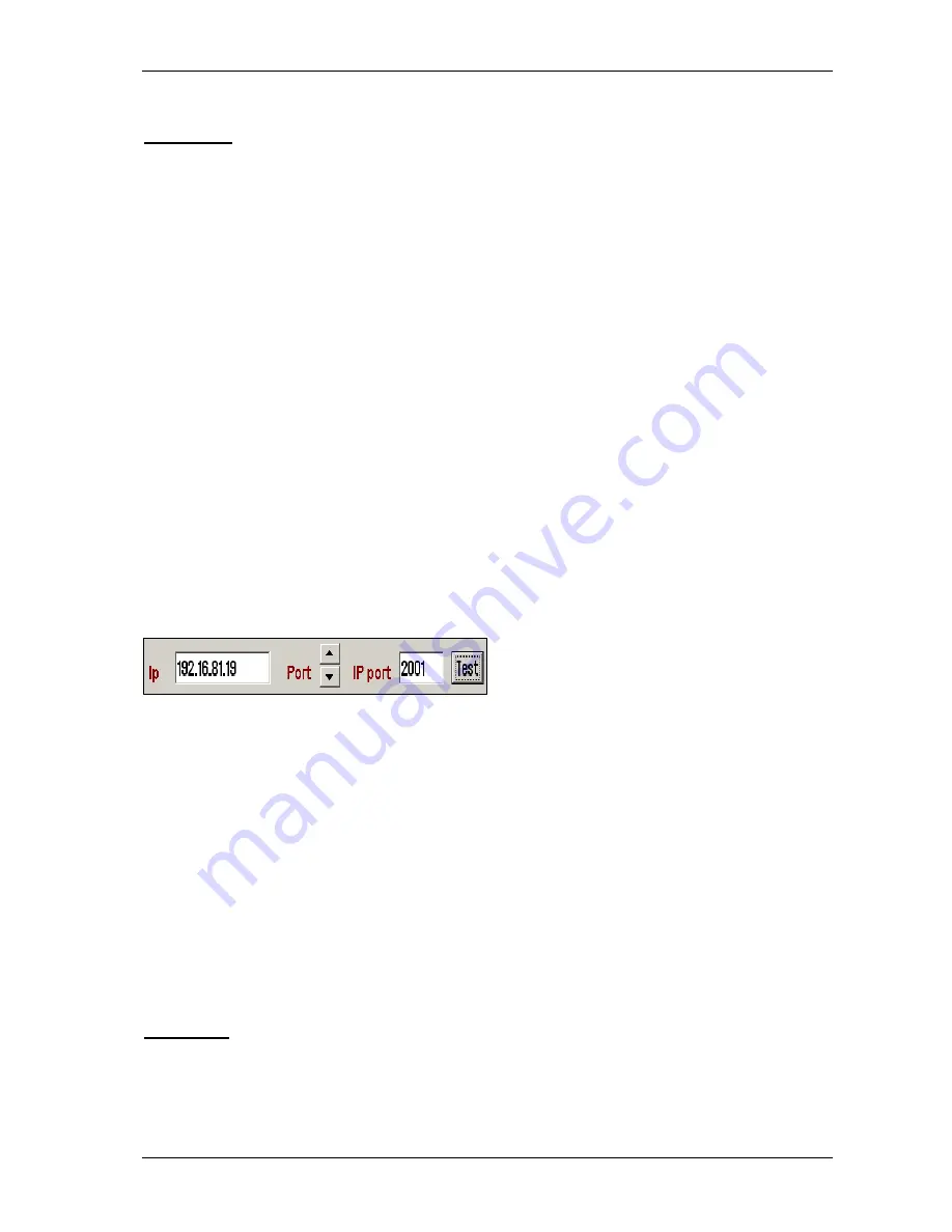
IP ports:
TECDIS has 12 COM ports and 4 IP
ports. For each IP port, the IP address and port
number must be entered. The “Test” button
establishes a connection to the IP server with the selected address/port number and the “Received
data” area will show any data that is received.
Example:
In order to receive position data from a GPS, you need to:
1.
Select “Position 1” or “Position 2” from the “Select sensor” column.
2.
Select the COM port the GPS is connected to in the “Port” field.
3.
Select the NMEA sentence type to be used.
4.
Optionally (but recommended) enter a description identifying the sensor as a GPS in the
“Sensor Description” field. If the sensor signal is lost while the TECDIS is in operation,
an alarm will be sounded. The alarm message will indicate the type of sensor lost as well
as what port it is connected to and the sensor description you enter in this field. This way,
you can quickly identify the failing instrument (instead of having to refer to the
configuration in the Setup program). NMEA Sensor inputs and their status can also be
displayed in TECDIS.
3.2.2 Speed
In this field you select the data speed to be used for the COM port of the currently selected
sensor. The NMEA standard is 4800 (low speed). Be aware though that some instruments require
a different data speed selection. There is also a NMEA high speed standard (38400). AIS units
Содержание TECDIS
Страница 8: ...TECDIS Installation Manual Page 7 Installation Overview...
Страница 18: ...TECDIS Installation Manual Page 17 Outline dimensions for HT 405P4 TEL A1 All figures in mm...
Страница 20: ...TECDIS Installation Manual Page 19 Furuno RCU 018 Control Unit outline Desktop mount All figures in mm...
Страница 22: ...TECDIS Installation Manual Page 21 Furuno RCU 018 Control Unit outline Flush mount...
Страница 32: ...TECDIS Installation Manual Page 31 2 1 Wiring diagram HT 405P4 TEL A1...
Страница 33: ...TECDIS Installation Manual Page 32 2 2 Signal distribution diagram internal data flow...
Страница 35: ...TECDIS Installation Manual Page 34 2 4 Ethernet connectors and cable...
Страница 36: ...TECDIS Installation Manual Page 35 2 5 Other connectors...
Страница 64: ...TECDIS Installation Manual Page 63 This page is intentionally left blank...
Страница 75: ...TECDIS Installation Manual Page 74 6 4 Installation Notes...
Страница 76: ...TECDIS Installation Manual Page 75...
Страница 79: ...TECDIS Installation Manual Page 78 This page is intentionally left blank...


