


4-2
3. Fix the power supply pcb (supplied) to the power module with four spacers (supplied).
4. Connect two VH connectors (provided on the power module) to the power supply pcb.
5. Lay the protection sheet (supplied) on top of the spacers and fasten with pan head
screws (M3×8).
6. Reattach the power module.
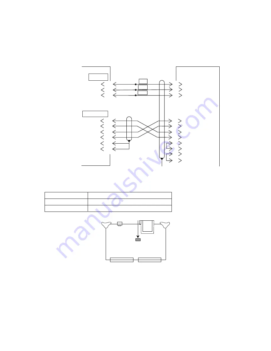
7. Connect between the processor unit and CS-120A as follows.
CS-120A
J201
PROCESSOR
UNIT
YEL
BRN
ORG
BRN
PPL BRN
L
E
PP
1
2
3
NN
MM
JJ
KK
1
2
3
4
5
6
BB
EE
DD
Z
24V
0V
GND
TD-H
TD-C
RD-H
RD-C
GND
DSR-C
DSR-H
DTR-H
+24V_H
+24V_C
GND
CIF_TXD_H
CIF_TXD_C
CIF_RXD_H
CIF_RXD_C
SHIELD
GND
37-core cable
10S1258
MJ-A3SPF0013-035
For CIF2
For CIF1
CS-120A
OR NMEA2/CIF2
Wiring between processor unit and CS-120A
8. Set the DIP switch on the DCON Board as follows.
Input port
DIP switch setting on DCON Board
CIF1 S3-#2:
ON
NMEA2/CIF2 S3-#3:
ON
S3
DCON Board (10P6987)
For connection to NMEA2/CIF2 port, the #8 segment of S2 on the IFES board should be
OFF (CIF).
Note:
If the CIF1 format is selected, change baud rate to 2400 bps. See CIF BAUD RATE
on page 3-8 for details.
Содержание FSV-84
Страница 1: ...COLOR SCANNING SONAR FSV 84 www furuno co jp ...
Страница 27: ...1 19 Fix the control box to bulkhead with four M10 bolts GND TERMINAL CABLE CLAMP FIXING HOLE TERMINAL ...
Страница 28: ...1 20 This page intentionally left blank ...
Страница 48: ...2 20 This page intentionally left blank ...
Страница 76: ...A 23 ...
Страница 77: ......
Страница 78: ......
Страница 79: ......
Страница 80: ......
Страница 81: ......
Страница 82: ......
Страница 83: ......
Страница 84: ......
Страница 85: ......
Страница 86: ...Nov 22 06 T Matsuguchi ...
Страница 87: ...Nov 22 06T Matsuguchi ...
Страница 88: ......
Страница 89: ...D 16 ...
Страница 90: ......
Страница 91: ...Mar 14 07 R Esumi ...


