3-4
3.7 Confirming Magnetron Heater Voltage
Magnetron heater voltage is adjusted at the factory wit h a 15 m signal cable.
Therefore, when the signal cable is longer than 15 m, confirm that magnetron
heater voltage is within the prescribed rating as follows:
1. Disconnect P821 from the scanner unit.
3. Turn on the radar and press [RADAR MENU] [0] [0] [0] [2] [0] to open the
INITIAL SETTING2 menu.
4. Press [5] to select the 5. SCANNER STOPPED field and the TX option.
5. Set the range to 0.125 nm.
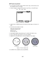
6. Turn off the antenna switch in the display unit.
PM
ON
OFF
TUNE
DEGAUSS ERROR
ANTENNA
switch
ANTENNA
Figure 3-5 Antenna switch in tuning compartment
7. Connect a multimeter, set to the 10 VDC range, between J829 #1 (+) and #2
(-) in the scanner unit.
8. Adjust the position of the sliding contact R812 to show a value between 7.0 V
and 7.6 V on the multimter.
9. Remove the TX-HV fuse (F801, 0.5A) from the power supply unit.
10.Transmit on maximum range.
11. Adjust the position of the sliding contact R811 to show a value between 4.7 V
and 5.3 V on the multimeter.
12.Insert TX-HV fuse F801.
13.Press [RADAR MENU] [0] [0] [0] [2] [0] [5] to select the 5. SCANNER STOPPED
field and the TX option.
14.Turn on the ANT MOTOR SW on the scanner unit (Refer to Figure 1-4).
Содержание FR-2165DS
Страница 1: ...MARINE RADAR MODEL FR 2165DS...
Страница 61: ......
Страница 62: ......
Страница 63: ......
Страница 64: ......
Страница 65: ......
Страница 66: ......
Страница 67: ......
Страница 68: ......
Страница 69: ......
Страница 70: ......
Страница 71: ......
Страница 72: ......
Страница 73: ......
Страница 74: ......
Страница 75: ......
Страница 76: ......
Страница 77: ......
Страница 78: ......
Страница 79: ......
Страница 80: ......
Страница 81: ......
Страница 82: ......
Страница 83: ......
Страница 84: ......
Страница 85: ......
Страница 86: ......
Страница 87: ......
Страница 88: ......
Страница 89: ......
Страница 90: ......
Страница 91: ......
Страница 92: ......


