15
4.4 Fabricating Cable, Assembling Connectors
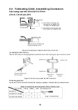
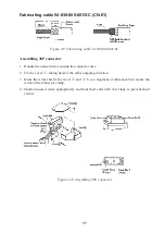
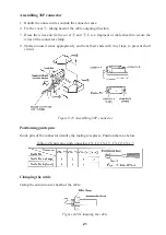
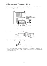
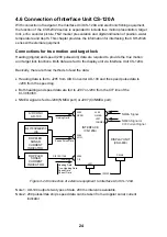
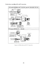
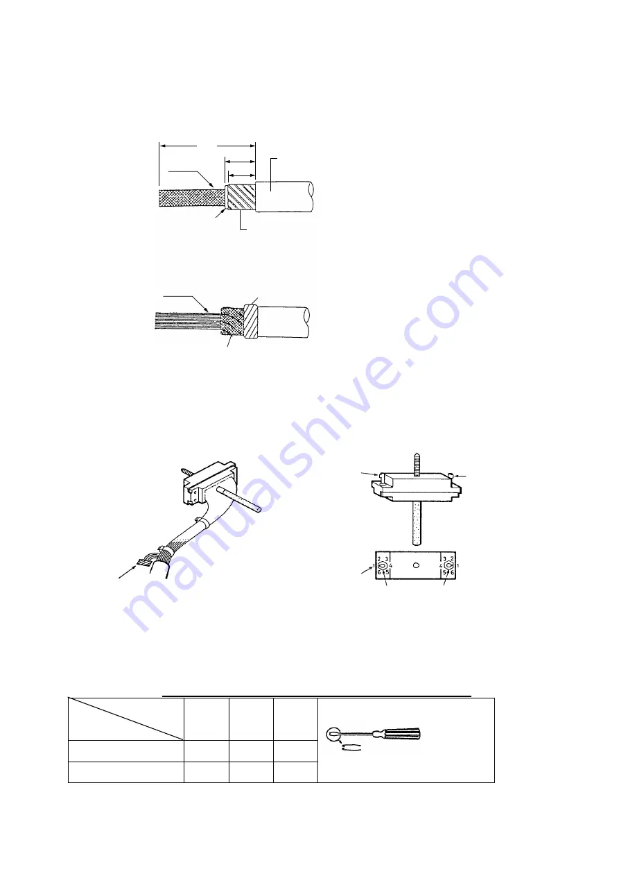
Fabricating cable 00-8016-038-313-761HV
(CN-A1, CN-A5 and J201)
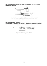
L
45
40
Anticorrosive
sheath
Armor
Vinyl sheath
Shield
Core
Insulating tape
Expose cores, and then wind
shield around the armor.
L = 250 (CN-A1) for Display Unit
320 (CN-A5) for Display Unit
170 (J201) for Interface Unit
L = 470 (CN-A1) for Processor Unit
440 (CN-A5) for Processor Unit
Figure 4-4 Fabrication cable 00-8016-038-313-761HV
Assembling the 38P connector
Shorten the unused wires appropriately and their ends with vinyl tape to prevent short circuit.
Insulate unused wires
with vinyl tape.
Guide Pin A
Guide Pin B
Position No.
Guide Pin A
(Large)
Guide Pin B
(Small)
Figure 4-5 How to assemble the 38P connector
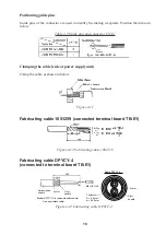
Positioning guide pins
Guide pins of the connector identify the mating receptacle. Position them as shown below.
Table 4-1 Guide pins and connectors CN-A1, CN-A5, J201
Connector
Guide Pin
CN-A1 CN-A5 J201
Guide Pin A (Large)
1
5
1
Guide Pin B (Small)
1
1
1
Positioning Tool
Type: 10-910-0179-0
Содержание CSH-23
Страница 1: ...COLOR SCANNING SONAR MODEL CSH 23 23F 24 24F Back ...
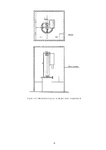
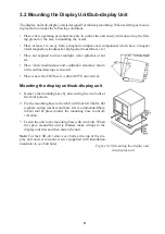
Страница 9: ...4 Figure 3 2 Maintenance space example sonar compartment ...
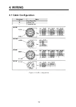
Страница 17: ...12 4 WIRING 4 1 Cable Configuration Figure 4 1 Cable configuration ...
Страница 53: ...A 4 ...
Страница 54: ...A 5 ...
Страница 61: ...A 12 ...
Страница 71: ...A 22 ...
Страница 72: ...A 23 ...
Страница 73: ...A 24 ...
Страница 74: ...A 25 ...
Страница 75: ...A 26 ...
Страница 76: ...A 27 ...
Страница 77: ...A 28 ...
Страница 78: ...A 29 ...
Страница 79: ......
Страница 80: ...D 2 ...
Страница 81: ...Y Hatai D 3 ...
Страница 82: ...D 4 ...
Страница 83: ...Oct 31 03 D 5 ...
Страница 84: ...D 6 ...
Страница 85: ...D 7 ...
Страница 86: ...D 8 ...
Страница 87: ...Dec 10 02 D 9 ...
Страница 88: ...D 10 ...
Страница 89: ...D 11 ...
Страница 90: ...D 12 ...
Страница 91: ...D 13 ...
Страница 92: ...D 14 ...
Страница 93: ...D 15 ...
Страница 94: ...D 16 ...
Страница 96: ...S 2 ...

