background image

- 45 -

11.

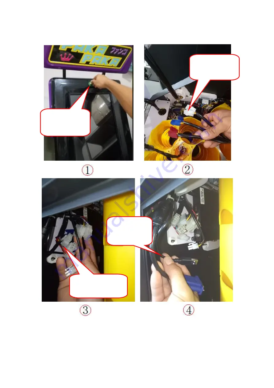
How to change the Mainboard?

Find the
keys(LG1)open
the screen

Separated the

blue,red,white

wire.

Open the front door,

Separated the

four different

Separated the

USB/VGA plug

Содержание 43014

Страница 1: ...4S Paka paka machine FCC ID 2AUBO43014 Model 43014 Isuue date Aug 27 2019 Caution Please read the manual carefully and keep it in mind before using this machine Put this manual within touch of your re...

Страница 2: ...use You can t put the game console near the emergency exit Protect game consoles from the following effects 1 Rain or damp places 2 Where the sun shines 3 Hazardous Flammable Material Places Do not p...

Страница 3: ...P14 7 2REPLACING DIAL P16 7 3REPLACING MAIN STRUCTURE P18 7 4HOW TO DISASSEMBLE TOP AND LIFT P21 8 HOW TO PLAY P22 8 1LOOP VIDEO P23 8 2 MAIN INFO P23 8 3PURCHASING INTERFACE P24 8 4 Info INTERFACE P2...

Страница 4: ...4 1 DIMENSION 2 SPECIFICATION DIMENSION W D H 500 635 2030 mm PACKING DIMENSION W D H 680 600 1570 mm GW KG 76 4KG NW KG 68 4KG VOLTAGE 120V FREQUENCY RANGE 60Hz CONSUMPTION 50W...

Страница 5: ...ARTS NO PART NAME PICTURE NO PART NAME PICTURE 1 billboard 9 lift 2 lock 10 Toys door 3 screen 11 Top rear board 4 Screen cover 12 Top holder 5 dial 13 handle 6 Coin selector 14 Rear door 7 volumn 15...

Страница 6: ...Capsule toy door 16 wheel NO PART NAME PICTURE NO PART NAME PICTURE 1 TYPE A 8 Main cabinet 2 Motor drive board 9 Token box 3 Mainboard 10 loudspeaker 4 Repair button 11 Setup part 5 TYPE B 12 Dial sp...

Страница 7: ...7 6 TYPE C 13 Dial switch 7 Power box...

Страница 8: ...8 4 LABEL LOCATION 4 1CAUTION LABEL LOCATION...

Страница 9: ...RE LABEL SIZE 1 nameplate L90mm W63mm 2 FCC L121mm W50mm 3 Do not open this door for non professional s L100mm W65mm 4 Indoor use only L133mm W65mm 5 Unplug before maintain L80mm W18mm 6 careful the c...

Страница 10: ...10 7 Maintenance outages L100mm W65mm 4 2 FUNCTION LABEL LOCATION NO PART NAME PICTURE 1 Insert token L60mm W37mm...

Страница 11: ...L47mm W37mm 4 Type A 50mm 5 Type B 50mm 6 Type C 50mm 7 Repair button 35mm 8 Set up L51mm W27mm 5 COMPOMENTS NO PART NAME SPEC QTY UNIT PICTURE REMARK 1 POWER LINE 1 5M 1 strip 2 PROTECTIVE TUBE 6 20...

Страница 12: ...12 4 MACHINE KEYS LG01 2 pcs 5 LOCK KEYS LG02 2 pcs 6 HEXAGON WRENCH 4mm 1 pcs 7 HEXAGON WRENCH 5mm 1 pcs...

Страница 13: ...loor and make sure that the product is installed stably in a horizontal position Installation of this product to ensure that the surrounding environment must be dry ventilated not damp The installatio...

Страница 14: ...WITH BLACK BOARD HOLD THE TOP BOX WITH TUBE INSERTED BETWEEN THE HOLES CHOOSE THE 4PCS SCREW USE THE HEXAGON WRENCH CONNECT THE TUBE WITH THE MAIN CABINET 6 3 HOW TO FILL IN TOYS INTO TOP USE THE SCRE...

Страница 15: ...15 PUT CAPSULE TOYS INSIDE THE HOLE SHOW AS FULL TOYS INSIDE COVER CIRCULAR PLATE USE THE SCREWDRIVER LOCK THIS 4 PCS SCREW 5 3 4 6...

Страница 16: ...16 7 HOW TO REPLACE MAJOR COMPONENTS 7 1TOP PART INSTALLATION DISGRAM...

Страница 17: ...hite 1 6 Corner code of plastic absorb ing cover 201 Stainless steel 1 7 Hexagonal screw in round cup M4 8mm 8 SN 03 06 8 Box shape Plastic absorb ing transparent organic cover 8 9 Back panel of box B...

Страница 18: ...18 7 2 DIAL PART INSTALLATION DISGRAM Drawing after Installation...

Страница 19: ...lon board 1 SN 06 06 4 Dial Rotating plate Q235 Galvanized 1 SN 02 05 5 Deep groove bearing 699ZZ 2 6 Dial bottom plate Q235 Galvanized 1 SN 02 06 7 Dial cushion gum Yellow polyurethane 1 SN 06 07 8 l...

Страница 20: ...20 7 3 CAPSULE TOYS STRUCTURE PART INSTALLATION DISGRAM...

Страница 21: ...l 4 SN 03 14 4 Four link Fixed Code for Support 201 Stainless steel 1 SN 03 15 5 Supporting rod fixing 201 Stainless steel 1 SN 03 14B 6 Large flat head machine silk M5 25mm Stainless steel 4 7 Token...

Страница 22: ...llow ABS 711 3 SN 07 02 16 Detection grating Electrolytic plate 1 5mm thick 3 SN 03 02 17 Bearing F688ZZ 3 18 threader stud 201 Stainless steel 9 SN 02 10 19 Micro DC Motor DC12V 5RPM 3 20 Motor fork...

Страница 23: ...23 7 4 TOP AND LIFT PART INSTALLATION DISGRAM NO PART NAME PICTURE SPEC QTY REMARK 1 Main cabinet Q235 1 SN 03 10 2 lift Q235 1 SN 03 12 3 Button board 15mm thick 2 4 Rubber foot pad High 25mm 2...

Страница 24: ...8 HOW TO PLAY 1 Loop video 2 Click the PUSH HERE TO START button at the bottom right of the screen to enter the main menu 3 There are three interfaces providing for you to select click the VIEW SERIES...

Страница 25: ...25 8 1 Loop video Video 1 video 2 Video 3 Tip click the PSHU HERE TO START button at the bottom right of the screen to enter the main menu when the video is showing 8 2 Main Menu...

Страница 26: ...26 8 3 Purchase interface Purchase interface No1 Purchase interface No 2...

Страница 27: ...27 Purchase interface No3 8 4 Info interface...

Страница 28: ...28 8 5 Purchase notification interface 8 6 Capsule notification interface...

Страница 29: ...29 8 7 Setting interface Attention Before entering the setting interface please use the key key type LG1 to open the front door and press the red button to enter the setting...

Страница 30: ...30 8 8 WIFI setting interface 8 9 Server IP address setting interface...

Страница 31: ...interface 8 11 Hardware test steps and errors handling Attention Before entering the hardware testing interface please follow the below steps one by one As shown below use the LG1 key to open the fron...

Страница 32: ...relation with machine broken down So please read this instruction seriously The hardware test is mainly used to check whether above hardware works normally or not The following below is to check wheth...

Страница 33: ...r The replacement process is following as below Use LG01 key to open the screen door Check whether each pipe has capsule or not and at least has one Hand touch to click the Test Motor A button If the...

Страница 34: ...he top two layers loose the red and blue docking ports loosen two screws on the sheet metal surface with a screwdriver Slowly pull out the 5 hole cover on the 5th floor of Sensor A Slowly pull out the...

Страница 35: ...he 5 hole cover on the third floor of Sensor A Slowly pull out the 5 hole cover on the second floor of Sensor A Select 5 5mm sleeve to loosen three nuts The sensor can be replaced by loosening the scr...

Страница 36: ...ollows Two sensors on both sides of the inclined plate of the ball are shielded by hand two on the left and two on the right Watch if Counter 2 is bright red Bright red indicates that the sensor is wo...

Страница 37: ...t Mechanism Hands will be gifts mechanism parts lifted at the same time to both sides of the screw position it is best to operate both front and back at the same time When the whole mechanism is lifte...

Страница 38: ...t Watch for bright red at Coins Bright red indicates that the coin operates normally Hand ope rated SW1 key loose the three screws of the slope mechanism and remove them Remove slope component status...

Страница 39: ...llows 4 SET UP BUTTON TEST Watch if the Set is bright red Bright red indicates that the button is working properly Hold the button by hand Pull the end of the wire by hand Choose the sleeve tool 7mm t...

Страница 40: ...t work properly a new button needs to be replaced The replacement steps are as follows Replacement of the new button will complete Remove the button docking terminal by hand loose the button screw wit...

Страница 41: ...st Watch Repair for bright red Bright red indicates that the button is working properly Turn the knob clockwise with your hand Watch for bright red at TURN Bright red indicates that the knob button is...

Страница 42: ...perly the knob switch should be replaced The replacement steps are as follows 8 12 Purchase Record Interface Release 2 screws with a screwdriver After pulling out the docking head The new knob switch...

Страница 43: ...following the below steps to update the APP version Use the LG01 key to open the front door press the red button Insert the USB to host The USB has contain the latest APP version Mainboard Select the...

Страница 44: ...en update it through the following steps As shown in the following figure Select Key Model LG01 Open the Door and Open the Front Door Press button Insert the latest APP program into the host USB plug...

Страница 45: ...45 11 How to change the Mainboard Find the keys LG1 open the screen Separated the blue red white wire Open the front door Separated the four different Separated the USB VGA plug...

Страница 46: ...46 Find this four butterfly nut loosen it Move out the wooden board Separated the mainboard plugs five place Use the screwdriver lose the four screw and then change the mainboard...

Страница 47: ...47 12 CIRCUIT DIAGRAM Note If the above illustrative pictures are changed the physical machine is the standard...

Страница 48: ...nt does cause harmful interference to radio or television reception which can be determined by turning the equipment off and on the user is encouraged to try to correct the interference by one or more...

Отзывы: