1-6-6
E9710DC
< Method 2 >
Note:
When servicing, do not touch white resin part
as shown below.
1. Remove the Top Cover, the Front Assembly and
the DVD Mechanism & DVD Main CBA Assembly.
Then, remove the DVD Mechanism Unit.
2. Remove two screws, and remove the Insulating
Plate.
3. Release two Locking Tabs, and lift up one side of
the Clamper Assembly.
4. Release the other side of two Locking Tabs, and
remove the Clamper Assembly.
5. Remove the disc.
Screw
Insulating Plate
Do not touch!
Locking Tabs
Clamper Assembly
Locking Tabs
Clamper Assembly
Disc
Содержание DRV-A2621
Страница 39: ...1 12 5 E9700SCM3 Main 3 9 Schematic Diagram VCR Section...
Страница 40: ...1 12 6 E9700SCM4 Main 4 9 Schematic Diagram VCR Section...
Страница 42: ...1 12 8 E9700SCM6 Main 6 9 Front Jack Schematic Diagram VCR Section...
Страница 44: ...1 12 10 E9700SCM8 Main 8 9 Schematic Diagram VCR Section...
Страница 45: ...1 12 11 E9700SCM9 Main 9 9 Schematic Diagram VCR Section...
Страница 47: ...1 12 13 E9700SCRJ Rear Jack Schematic Diagram VCR Section...
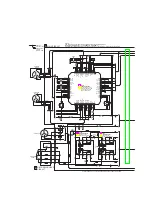
Страница 49: ...1 12 15 E9700SCD1 DVD Main 1 6 Schematic Diagram DVD Section...
Страница 50: ...1 12 16 E9700SCD2 DVD Main 2 6 Schematic Diagram DVD Section...
Страница 51: ...1 12 17 E9700SCD3 DVD Main 3 6 Schematic Diagram DVD Section...
Страница 86: ...DRV A2621 DRV A2677 DRV A2631 DRV B2737 E9700 04 07 05ED 2005 06 23...


