5-2
A8C70EA
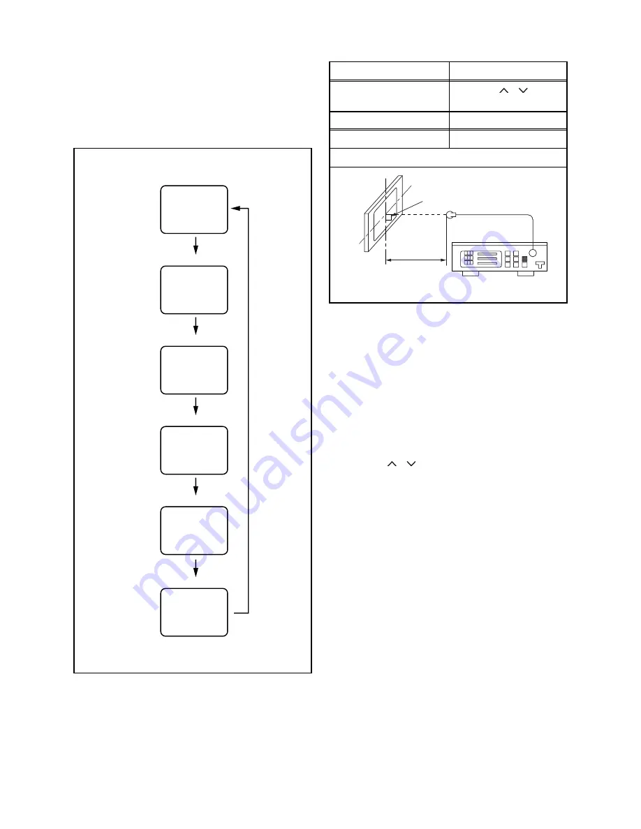
1. Purity Check Mode
This mode cycles through full-screen displays of red,
green, blue, and white to check for non-active pixels.
1. Enter the Service mode.
2. Each time pressing [7] button on the service
remote control unit, the display changes as
follows.
2. VCOM Adjustment.
1. Operate the unit for more than 20 minutes.
2. Set the color analyzer and bring the optical
receptor to the center on the LCD-Panel surface
after zero point calibration as shown above.
Note:
The optical receptor must be set
perpendicularly to the LCD Panel surface.
3. Enter the Service mode.
4.
[VCOM1]
Press [2] button on the service remote control unit.
[VCOM2]
Press [3] button on the service remote control unit.
5. Press [P
/
] buttons on the service remote
control unit so that the color analyzer value
becomes minimum.
[7] button
Note:
When entering this mode, the default setting is White mode.
Purity Check Mode
[7] button
Red mode
Green mode
Blue mode
Black mode
[7] button
White mode
[7] button
[7] button
White 25% mode
[7] button
Test Point
Adj. Point
Screen
[P
/ ]
buttons
M. EQ.
Spec.
Color analyzer
See below
Figure
Color Analyzer
It carries out in a darkroom.
L = 3 cm
Perpendicularity
Содержание A8C72EP
Страница 29: ...8 3 A8C72SCM1 Main 1 3 Schematic Diagram ...
Страница 30: ...8 4 A8C72SCM2 Main 2 3 Jack Schematic Diagram ...
Страница 32: ...8 6 A8C72SCINV Inverter Junction Schematic Diagram ...
Страница 33: ...8 7 Function Schematic Diagram A8C72SCF ...
Страница 34: ...8 8 IR Sensor Schematic Diagram A8C72SCIR ...
Страница 39: ...8 13 A8C72SCD5 Digital Main 5 6 Schematic Diagram ...
Страница 43: ...8 17 BA8A70F01021 1 Inverter CBA Top View ...
Страница 44: ...8 18 BA8A70F01021 1 Inverter CBA Bottom View ...
Страница 46: ...8 20 Jack CBA Top View Jack CBA Bottom View BA8C72F01012 4 Junction CBA Top Bottom View BA8A70F01021 ...
Страница 64: ...LT6 M22BB LT6 M22WB A8C72 73EP 2008 11 26 ...


