

Indication offset
Allows to compensate an eventual variation of pressure readings caused by sensor replacement.
RS485 network controller address
®
Device address in the network for communication with Sitrad software application.
Warning:
it is not allowed to have more than one device with the same address in a network.
5. AUTOTUNING
The
AutoPID
plus
uses the Critical Period method to calculate automatically its PID parameters. This
method consists in making the system temperature oscillate around the setpoint so that the necessary
data can be collected to adjust the controller. The user must input two parameters for the method to work
properly: Temperature Hysteresis (F09) and Output Amplitude (F08). Both parameters must be chosen
to permit a recognizable oscillation around the setpoint. The autotuning operation time will vary for each
response from the system. Systems with a bigger cooling/heating capacity will have quicker responses
and the autotuning function will finish the data collection quicker.
The method for starting the autotuning can be configured in the function F11 and may operate in the
following modes:
Manual activation:
The autotuning can be activated either through the controller keyboard or through
®
the Sitrad software.
When activating the automatic control:
The autotuning will be executed every time the controller
enters the automatic control mode (PID).
Temperature not steady:
The autotuning will be executed every time the temperature does not
stabilize inside the time period programmed in the function F12.
When activating the automatic control and the temperature is not steady:
The autotuning will be
executed every time the controller enters in the autotuning mode and when the temperature does not
stabilize inside the time period programmed in the function F12.
If an error occurs during the system data collection, the controller will interrupt the autotuning and emit
an alarm with the message . Then it returns to the operation mode set before the autotuning
activation.
6. EASY ACCESS FUNCTIONS
6.1 - Proportional output value indication
Press the key shortly for displaying the current proportional output value. The percentage value will
be displayed followed by the indication .
SET
6.2 - Minimum/Maximum temperature indication
Press shortly to display the minimum/maximum temperature. When pressing the key, the message
will be displayed indicating the sensor temperature followed by the indication . If you hold the
key pressed, the values are restarted and the message is displayed.
6.3 - Controller operation mode selection
Hold the key pressed for 4 seconds to choose the controller operation mode. After pressing the key,
the message will be displayed followed by the current operation mode. Use the and keys
to choose one of the following options:
Controller OFF
Controller in the manual mode
Controller in the automatic mode
Use the key to confirm the selection and wait the message indicating that the setting is
finished.
6.4 - Canceling the active alarms
Press the key shortly to cancel the indication of current active alarms. After pressing the key, the
message is displayed and all the current active alarms will be deactivated.
SET
6.5 - Autotuning manual activation/deactivation
You can activate or deactivate the PID parameter autotuning by holding the key pressed for 2
seconds. The message will be displayed followed by the message (for activating) or
(for deactivating). When manually activating the autotuning, its starting conditions described in
item 5 will not be tested.
7 - DISPLAY MESSAGES
Low temperature alarm
High temperature alarm
Autotuning error
Indicates the autotuning was not completed after 12 hours.
Indicates an error occurred in the parameter calculation during the autotuning.
Indicates an error occurred in the temperature reading during the automatic control.
Temperature sensor disconnected or out of range
Invalid parameters configuration
The outputs are turned off automatically in this situation
Please check which parameters have invalid data configured and correct them to return to
normal operation
Open collector
8. CONNECTION
4
5
6
7
8
9 10 11 12
3
2
1
2
1
Se
ns
or
90 264V
ac (50/60Hz)
GND
12V Output
Red
0 10Vdc
Black
ALRM
For a current higher than the specified value,
use a power relay for activating the alarm.
RS
48
5 S
er
ial
co
m
m
un
ica
tio
n
Proportional voltage output
Proportional PWM output
Power supply
Alarm power
supply
T
o the terminal of
the distribution box
A
B
IMPORTANT
According to the chapters from the IEC60364 standard:
1:
Install protectors against over voltage on power supply
2:
Sensor cables and computer signals can be together, however not at the same place where power
supply and load wires pass for
3:
Install suppresor of transient in parallel to loads to increase the usefull life of the relays
Wiring diagram of suppresors in contactors
Suppresor
A1
A2
A1 e A2 are the
contactor coils.
Wiring diagram of suppresor for direct drive
Load
Suppresor
For direct activation the maximum
specified current should be taken
into consideration.
ENVIRONMENTAL INFORMATION
Package:
The packages material are 100% recyclable. Just dispose it through specialized
recyclers.
Products:
The electro components of Full Gauge controllers can be recycled or reused if it is
disassembled for specialized companies.
Disposal:
Do not burn or throw in domestic garbage the controllers which have reached the end-of-
life. Observe the respectively law in your region concerning the environmental
responsible manner of dispose its devices. In case of any doubts, contact Full Gauge
controls for assistance.
PROTECTIVE
:
VINYL
This adhesive vinyl (included inside the packing) protects the instruments against
water drippings, as in commercial refrigerators, for example. Do the application after
finishing the electrical connections.
Remove the protective paper
and apply the vinyl on the entire
superior part of the device,
folding the flaps as indicated by
the arrows.
Dimension of the clipping
for setting of the instrument
in panel
29 mm
72 mm
A
A
B
B
A B
A
B
A
B
A
B
OUT
1
OUT 2
OUT 3
PCT-400R plus
OUT 4
ALMR
A
A
B
B
A B
A
A
B
B
A B
A
A
B
B
A B
A
A
B
B
A B
PUMP
AUX
1
AUX 2
MICROSOL II plus
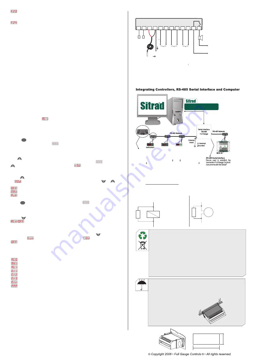
*Connecting Block for Serial Communication
Used to connect more than one instrument to the Interface. The wire's connections must
be made in agreement with the following rules: terminal
A
of the instrument connects to
the terminal
A
of the c
, that must be connected with the terminal
A
of the
Interface. Repeat the action for terminals
B
and
, being
the cable shield.
onnecting block
the terminal
must be connected to the respective terminals of
each instrument.
of connecting block
Keep Sitrad updated in website:
http://www.sitrad.com
®
*Sold Separately


