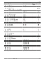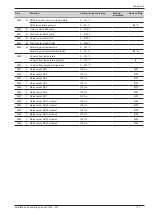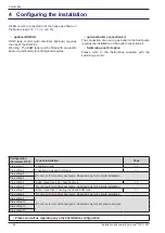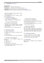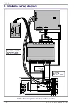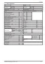
5 Electrical wiring diagram
figure 20 - Electrical wiring of Control Box (except installer's connections)
1a
2a
1b
2b
BK
WH
RD
GN
BK
WH
RD
GN
RT
KECS
L N
N QX3
QX5 QX6 QX7
UX U
ref
H1 H3
X30
DO1 DO2 M BX4 BX5
1
L
2
N
3
COM
4
5
6
7
8
N
9
L
10
11
12
L
13
N
14
L
15
N
OUTDOOR
UNIT
BOILER
CONNECT
.
BOILER
VAL
VE
DHW
. BACK UP
SUPPL
Y
DHW
. BACK UP
CONNECT
16
17
18
L
19
N
Connections to regulator,
accessories and options
Connections
to terminals
)
Start/stop
switch
Installation and operating manual "1395 - EN"
Control Box
- 34 -


