7-6
System Power
an interrupt, the system returns to the Fully On state. If the Idle Mode option is disabled in the BIOS, the
system will not enter Idle mode.
* Power saving timeouts can be configured independently for these devices allowing them to enter a low-power
state while the system is in Idle mode.
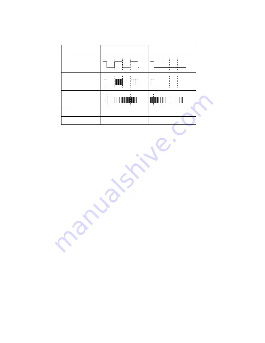
Note that this table does not depict a precise timing diagram. The illustrations given in this table are intended to
show the relative characteristics of these signals.
Standby Mode
Standby mode is entered when the Standby Mode Timeout (configured in the BIOS) occurs. In Standby
mode, the CPU, supporting chip set, and RAM remain powered, however, the CPU’s internal clock
signals are stopped (effectively stopping the CPU) as indicated in Table 7-3. Any user activity that
generates an interrupt will cause a transition out of the Standby state to the Fully On state.
The hard disk drive is forced into standby mode (spun down) when the standby mode timeout occurs.
Note, however, that the hard disk drive can be configured to spin down earlier by setting the HDD
Spin-down Timeout BIOS option. The display system (including backlight) is also turned off when the
standby timeout occurs. The display can also be configured to turn off earlier by setting the Video
Timeout BIOS option.
Suspend Modes
The system can be configured to use one of two different suspend modes: Suspend-to-RAM or
Suspend-to-Disk. System power activity in each of these modes is described below.
Suspend-to-RAM Mode
In Suspend-to-RAM mode, power is maintained to RAM, video memory, and circuitry for the Suspend/
Resume button while all other system circuitry and power managed devices are powered off. The PC
Card slots will also remain powered if the Resume On Modem Ring option is enable in the BIOS. Pressing
the Suspend/Resume button, or a resume request generated by a modem ring will cause a transition to
the Fully On state. Suspend-to-RAM mode is best suited for applications where system operation is
suspended frequently and a quick resume is desired.
Table 7-3 System Activity in Idle and Standby Modes
System Activity
Idle Mode
Standby Mode
Stop Grant
(STPCLK#)
Internal CPU Clock
Signals
External Clock
Signals
Hard Disk Drive
On*
Standby (spin down)
Display On*
Off
Microsoft Corp. Exhibit 1020
Содержание Stylistic 2300
Страница 1: ...Microsoft Corp Exhibit 1020 ...
Страница 8: ...viii Microsoft Corp Exhibit 1020 ...
Страница 10: ...x Microsoft Corp Exhibit 1020 ...
Страница 18: ...1 4 Pen Tablet Features Microsoft Corp Exhibit 1020 ...
Страница 42: ...Microsoft Corp Exhibit 1020 ...
Страница 60: ...3 40 Configuring the Stylistic 2300 Pen Tablet System Microsoft Corp Exhibit 1020 ...
Страница 61: ...Microsoft Corp Exhibit 1020 ...
Страница 63: ...Microsoft Corp Exhibit 1020 ...
Страница 74: ...5 10 Hardware Specifications Microsoft Corp Exhibit 1020 ...
Страница 76: ...Microsoft Corp Exhibit 1020 ...
Страница 77: ...Microsoft Corp Exhibit 1020 ...
Страница 78: ...Microsoft Corp Exhibit 1020 ...
Страница 81: ...Microsoft Corp Exhibit 1020 ...
Страница 91: ...Microsoft Corp Exhibit 1020 ...
Страница 114: ...9 4 Programmable Hotpad Libraries for 16 bit Windows Applications Microsoft Corp Exhibit 1020 ...
Страница 120: ...Microsoft Corp Exhibit 1020 ...
Страница 124: ...C 2 Enabling ACPI Microsoft Corp Exhibit 1020 ...
Страница 138: ...Index 6 Microsoft Corp Exhibit 1020 ...
Страница 139: ...Microsoft Corp Exhibit 1020 ...
Страница 140: ...4 99 58 0584 00C Microsoft Corp Exhibit 1020 ...


