background image

Page 54 of 64 


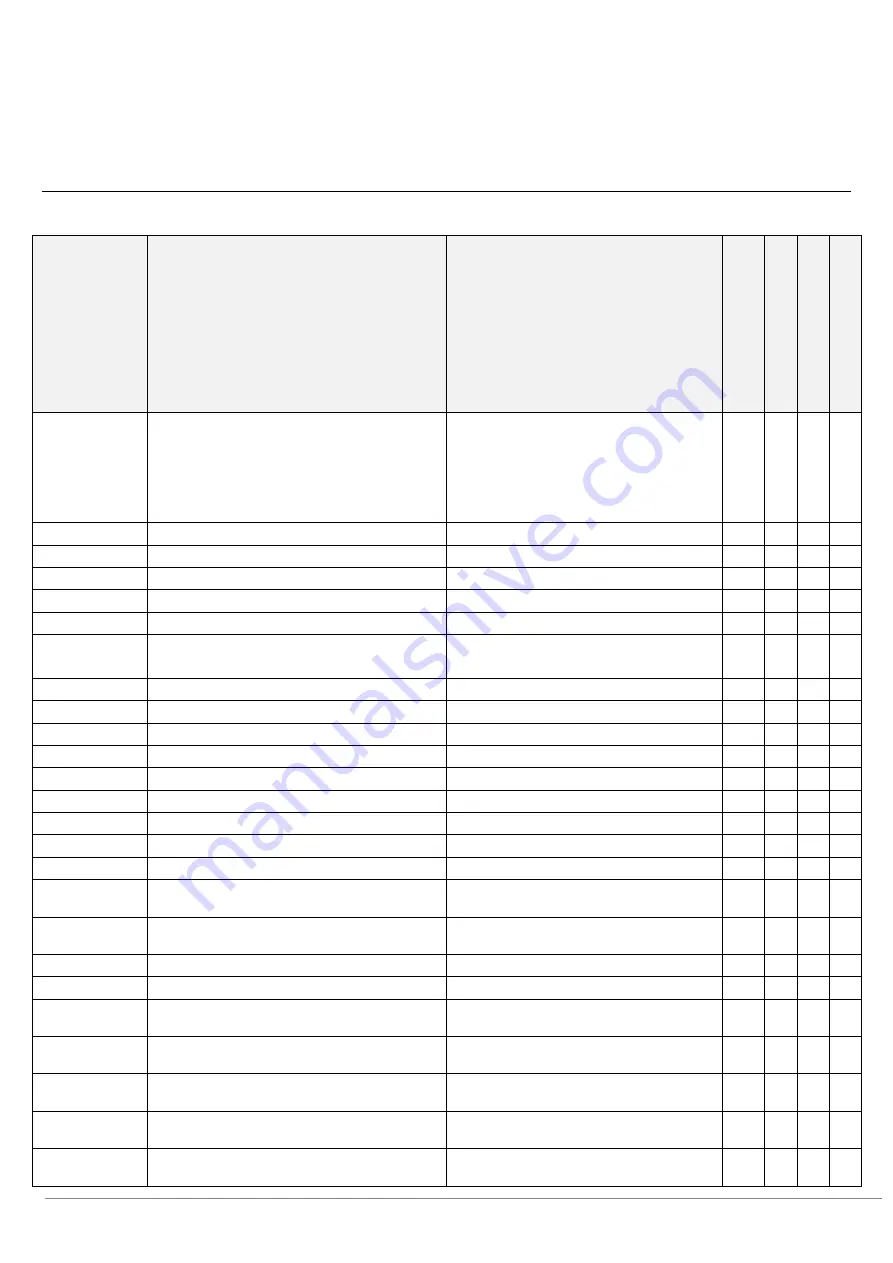
Spare parts and exploaded-view drawings STYLISTIC Q7310 


Drawing 

number 

Spare part 

Internal spare part name for ordering 

C

u

sto

mer

 r

ep

la

ce

ab

le


p

ar

ts


Se

rv

ic

e r

ep

la

ce

ab

le

 pa

rts


Up

gr

ad

ea

b

le


Rep

ai

ra

b

le


Mechanical parts: 


11 

LCD back cover 

 
depending on the device configuration 


20 

Corner rubber covers 

Corner round cover (grip) 


78 

SIM tray 


82 

AC adapter 


48 

Main battery 


53 

DC-in connector 


41 

Pen garage 


80 

Mass storage (e.g. SSD, M.2 module) 

depending on the device configuration 


Cooling:   


45 

  fan 


30 

Mainboard   

depending on the device configuration 


76 

LTE module 


44 

SmartCard reader 


10 

LCD module 

depending on the device configuration 


32 

CMOS battery 


13 

Pen 


40/16/17 

Camera (rear, front) 


19 

Docking connector 


21 

Inner support plate 


25/26/27/28/29 

Covers (e.g. USB port, HDMI port, Audio port, 
SIM slot) 


Sub board (e.g. cameras, audio/USB, 
application buttons) 

depending on the device configuration 


Cables, flex print cables and antennas 

depending on the device configuration 


Fingerprint sensor: replaceable by echange of 
LCD back cover 


Speakers: replaceable by exchange of inner 
support plate 


Main memory/ RAM: onboard, replaceable by 
exchange of the mainboard 


Processor: CPU is replaceable by exchange of 
the mainboard 


Graphics card: is part of CPU and is replaceable 
by exchange of the mainboard 


Содержание Q7310MC5BMIN

Страница 1: ...nnas 24 Remove LTE module 26 Remove the camera module 28 Removing the rear camera 30 Removing the camera sub board 31 Removing the front camera 32 Remove SAR antennas 33 Removing the WLAN antennas 35 Remove CMOS battery 37 Removing the USB audio sub board 38 Removing the fingerprint sensor 40 Remove corner rubbers 41 Remove fan 42 Removing the DC in connector 43 Removing the SmartCard reader 44 Re...

Страница 2: ...onents The device must be switched off when installing removing components and it must not be in power saving mode Disconnect the mains plug before opening the device After unplugging the mains plug discharge the remaining voltage by pressing the activation button Remove all externally connected cables Take care not to pinch any cables when installing removing components Please ensure that the ins...

Страница 3: ... use items with sharp edges screwdrivers to lever them out Parts with Electrostatic Sensitive Devices ESD can be identified by a corresponding label When dealing with boards with ESDs the following points must always be observed Always ensure there is a static discharge e g by touching a grounded object prior to commencing with the work The devices and tools being used must not be statically charg...

Страница 4: ...5XL3 D4 5 Screwdriver Phillips PH00 Screw M2 5XL4 Screwdriver Phillips PH00 Screw M2 5XL6 D4 5 Screwdriver Phillips PH00 Screw M2XL2 5 Screwdriver Phillips PH00 Screw M3XL3 5 1 Screwdriver Phillips PH00 Return to Table of Contents ...

Страница 5: ...Page 5 of 64 Tools Screwdriver Phillips size PH00 Plastic tool Plastic tool Return to Table of Contents ...

Страница 6: ...om its keyboard by pressing the release button yellow arrow and pulling the STYLISTIC Q7310 upwards green arrows To reconnect the STYLISTIC Q7310 to its keyboard gently refit the tablet on it red arrows The guidance indicator blue circle on the tablet and keyboard will support you to find the correct position The keyboard of the STYLISTIC Q7310 can be ordered as a module Return to Table of Content...

Страница 7: ...from its cradle by pressing the release button yellow arrow and pulling the STYLISTIC Q7310 upwards green arrows To reconnect the STYLISTIC Q7310 to its cradle gently refit the tablet on it red arrows The guidance indicator blue circle on the tablet and cradle will support you to find the correct position The cradle of the STYLISTIC Q7310 can be ordered as a module Return to Table of Contents ...

Страница 8: ...ottom right next to the keyboard connector Open it green arrow and remove the SIM card holder yellow arrow Pull out the SIM card holder in the yellow arrow direction Please note To ensure proper positioning the SIM tray must be inserted horizontally into the SIM card slot see figure above Return to Table of Contents ...

Страница 9: ... the pen Pull the pen straight out of the pen garage green arrow The pen can be attached with a ribbon running through the eyelet red rectangle under the pen garage Undo it to be able to replace the pen Return to Table of Contents ...

Страница 10: ... Minimum requirements to properly finalise hardware repairs on mobile systems SB M 15007 WIN8x WIN10 Spare product key for repaired devices For any information about ESD please refer to the web based training course ESD in electronics Service Partner only login required ...

Страница 11: ...ommencing with the work The devices and tools being used must not be statically charged Only touch the components along the edges or on the areas marked in green contact points Contacts and electronic components must not touch when handling components equipped with ESD protection Further information can be found in the chapter Information on the installation and removal of components Remove the fo...

Страница 12: ... bit Start to do so on the sides or from the bottom yellow arrows red border as shown on the next page Now lift the LCD back cover assy and turn it over green arrows Be careful as two cables are still connected to the mainboard see picture on the next page Please note Careless movements when separating the LCD back cover assy from the STYLISTIC could damage the connectors on the mainboard that are...

Страница 13: ...aut First carefully disconnect the battery cable from the battery red circle Carefully disconnect the SiBeam flexprint cable yellow circle This cable is integrated in the LCD back cover assy Disconnect the fingerprint flexprint cable orange circle Return to Table of Contents Service Partner only ...

Страница 14: ...d Remove cradle Remove pen Removing the LCD back cover assy Required tools Screwdriver Phillips size PH00 Remove the three M2XL3 screws yellow circles Remove the battery from the device direction of the green arrows Return to Table of Contents Service Partner only ...

Страница 15: ...2 module Required work steps Remove keyboard Remove cradle Remove pen Removing the LCD back cover assy Remove battery Required tools Screwdriver Phillips size PH00 Remove the M2XL2 5 0 screw yellow circle Service Partner only ...

Страница 16: ...movements It can then be easily pulled upwards and removed blue arrow Please note Due to the M 2 interface no conventional HDDs or SSDs with a common form factor can be used in the STYLISTIC Q7310 Return to Table of Contents Service Partner only Service Partner only ...

Страница 17: ...emove keyboard Remove cradle Remove pen Removing the LCD back cover assy Remove battery Required tools Screwdriver Phillips size PH00 Disconnect the flexprint cable of the docking connector yellow circle Remove the two M2XL2 5 screws blue circles Service Partner only ...

Страница 18: ...e the docking connector by moving it in the direction of the arrow yellow As soon as you have carefully pulled it out of the recess provided you can lift it out green arrows Return to Table of Contents Service Partner only ...

Страница 19: ...ps size PH00 Remove the screw M2XL3 yellow circle Remove the adhesive tape and the cable red flashes The cable of a SAR antenna red rectangle runs through the cable duct yellow arrows of the pen garage and must therefore be disconnected orange circle On the following page you will find the detailed view Remove the pen garage from the device green arrow Service Partner only ...

Страница 20: ...Page 20 of 64 After successful replacement route the SAR antenna cable through the designated duct yellow arrow Return to Table of Contents Service Partner only ...

Страница 21: ...ing the LCD back cover assy Remove battery Remove pen garage Required tools Screwdriver Phillips size PH00 Remove the two screws M2XL3 yellow circles Disconnect the flexprint cable red circle Take the application button sub board out of the device see arrow direction green Return to Table of Contents Service Partner only ...

Страница 22: ...ove keyboard Remove cradle Remove pen Removing the LCD back cover assy Remove battery Required tools Screwdriver Phillips size PH00 Release and carefully remove the cover for button section the single keys and the holder for button set from their intended positions yellow arrows Service Partner only ...

Страница 23: ...ull the four nubs of the holder for button set blue rectangle out of the provided recesses yellow circles Below you can see a picture with a top view of these recesses Return to Table of Contents Service Partner only ...

Страница 24: ...ve pen garage Remove the application key sub board Required tools Screwdriver Phillips size PH00 Picture 1 Remove the two screws M2XL3 yellow circles The WWAN antennas are marked by red rectangles The LTE module is located under the gasket blue rectangle Release the two connector locks yellow rectangles and remove the flexprint cable Service Partner only ...

Страница 25: ...e yellow cable must be connected to the MAIN port and the orange one to the AUX port yellow MAIN orange AUX Warning The antenna cables are routed through a cable duct into the camera module yellow arrow picture 2 Please put the antenna cables in their original positions when reassembling The third antenna shown picture 3 is one of the two SAR antennas red rectangle which must be disconnected from ...

Страница 26: ...e LCD back cover assy Remove battery Required tools Screwdriver Phillips size PH00 Disconnect and remove the flexprint cable which is fitted over the LTE module and leads to the camera sub board yellow circles Put aside the gasket to the right green arrow The LTE module is now visible Service Partner only ...

Страница 27: ...ue arrow Warning The antenna cables are routed through a cable duct into the camera module yellow arrow Please put the antenna cables in their original positions when reassembling Please note When fitting the LTE module make sure that both antenna cables are properly connected The yellow cable must be connected to the MAIN port and the orange one to the AUX port yellow MAIN orange AUX Return to Ta...

Страница 28: ... the right blue arrow Disconnect the flexprint cables connected to the camera sub board yellow circles The SAR antenna cable and the WWAN antenna cable run through the cable duct yellow arrow of the camera module Disconnect the two SAR antenna cables red rectangle from the mainboard and lay them together with the yellow WWAN antenna cable MAIN outside the work area green arrow Remove both M2XL3 sc...

Страница 29: ... When the position shown above has been reached the module can be lifted out green arrow This module connects different components which can be ordered separately The next chapters describe how to disassemble each single component Return to Table of Contents Service Partner only ...

Страница 30: ...ery Remove LTE module Remove the camera module Required tools Screwdriver Phillips size PH00 The module of the rear camera is connected with a flexprint cable on the sub board of the camera module yellow rectangle Disconnect this cable and run the rear camera module out of the module green arrow Return to Table of Contents Service Partner only ...

Страница 31: ...attery Remove LTE module Remove the camera module Removing the rear camera Required tools Screwdriver Phillips size PH00 Plastic tool Use a plastic tool screwdriver or your fingers to release the two plastic brackets yellow circles By pressing these sideways the sub board can be lifted and removed Return to Table of Contents Service Partner only ...

Страница 32: ...cover assy Remove battery Remove LTE module Remove the camera module Required tools Screwdriver Phillips size PH00 Plastic tool Carefully release and lift the camera module in several points yellow arrows with a plastic tool and disconnect it from its frame holder green arrow Return to Table of Contents Service Partner only ...

Страница 33: ... WWAN antennas Remove the camera module Required tools Plastic tool One SAR antenna blue rectangle is integrated in the bracket of the WWAN antenna yellow rectangle the other SAR antenna red rectangle is located over the camera module purple rectangle Please consider all the necessary steps especially those described in chapter Removing the WWAN antennas and Removing the camera module Service Part...

Страница 34: ... antenna from the WWAN antenna red rectangle Use a plastic tool if necessary Release the second SAR antenna blue rectangle from the camera module Use a plastic tool if necessary Return to Table of Contents Service Partner only Service Partner only ...

Страница 35: ...uired tools Screwdriver Phillips size PH00 Remove the two M2XL3 screws yellow circle Disconnect both WLAN antenna cables red circles It may be necessary to remove the adhesive tape and the cable from the pen garage red flash After replacement the cables must be returned to their intended positions yellow arrows Service Partner only Service Partner only ...

Страница 36: ...WLAN antennas make sure that both antenna cables are properly connected The grey cable must be connected to the AUX port and the black one to the MAIN port grey AUX black MAIN Return to Table of Contents Service Partner only Service Partner only ...

Страница 37: ...tools Screwdriver Phillips size PH00 Disconnect the cable yellow circle Carefully remove the CMOS battery red rectangle and the associated cable Please note It can be ordered separately Supplied together with the mainboard After assembling the cable must be returned to its original position yellow arrows Return to Table of Contents Service Partner only ...

Страница 38: ...D back cover assy Remove battery Required tools Screwdriver Phillips size PH00 Disconnect both flexprint cables red circles Carefully disconnect the pen garage cable yellow circle Remove the three M2XL2 5 0 screws blue circles The audio panel is now loose and can be removed in the green arrow direction Service Partner only ...

Страница 39: ...Page 39 of 64 Afterwards the USB audio sub board can be removed in the green arrow direction Return to Table of Contents Service Partner only ...

Страница 40: ...this information when you use the fingerprint sensor The figure above shows a device configuration with fingerprint sensor yellow rectangle When the fingerprint sensor is used the fingerprint sub board is integrated in the LCD back cover assy LCD back cover for SIM W FP and must be completely replaced if defective The fingerprint sub board is not available separately Return to Table of Contents Se...

Страница 41: ...uired work steps Remove keyboard Remove cradle Remove pen Removing the LCD back cover assy Remove battery Required tools Screwdriver Phillips size PH00 Lift each corner rubber from its bracket Return to Table of Contents Service Partner only ...

Страница 42: ...Required tools Screwdriver Phillips size PH00 Remove both screws M2XL3 yellow circles The cable of the fan connector may be a bit difficult to disconnect red circle In this case try disconnecting it with two tools figure below Carefully lift the fan out green arrow Return to Table of Contents Service Partner only Service Partner only ...

Страница 43: ...e cradle Remove pen Removing the LCD back cover assy Remove battery Required tools Screwdriver Phillips size PH00 Disconnect the connection cable from the mainboard red circle Pull out the DC in connector green arrow Return to Table of Contents Service Partner only Service Partner only ...

Страница 44: ...Required work steps Remove keyboard Remove cradle Remove pen Removing the LCD back cover assy Remove battery Required tools Screwdriver Phillips size PH00 Disconnect the cables yellow circles Remove the M2XL3 screw red circle Service Partner only ...

Страница 45: ...Page 45 of 64 Push the SmartCard reader slightly upwards blue arrow Lift the SmartCard reader green arrow Return to Table of Contents Service Partner only ...

Страница 46: ...le the M 2 module the SIM tray and the connecting cable between the main board and the battery The new mainboard is supplied with a mounted heatsink integrated TPM module WLAN module and working memory and a CMOS battery Remove all cards or plastic dummies e g SIM card SD card etc and the relevant pen Disconnect the SAR and WLAN antenna cables the fan cable the cable of the CMOS battery and the ca...

Страница 47: ... the device if no module is installed make sure to protect the antenna cables from possible short circuits e g with ESD adhesive tape The mainboard is always supplied with a heatsink The connecting cable between the mainboard and the battery red rectangle can be ordered separately and must be removed from the main board Return to Table of Contents Service Partner only Service Partner only Service ...

Страница 48: ...board Removing the WWAN antennas Remove SAR antennas Removing the WLAN antennas Remove CMOS battery Removing the USB audio sub board Remove corner rubbers Remove fan Removing the SmartCard reader Remove mainboard Required tools Screwdriver Phillips size PH00 If it is necessary to replace the LCD assy release the covers red rectangle by guiding them through the recesses yellow rectangles lower pict...

Страница 49: ...Page 49 of 64 Please note These covers are not supplied as part of the LCD assy Return to Table of Contents Service Partner only ...

Страница 50: ...tion key sub board Removing the WWAN antennas Remove SAR antennas Removing the WLAN antennas Remove CMOS battery Removing the USB audio sub board Remove corner rubbers Remove fan Removing the SmartCard reader Remove mainboard Required tools Screwdriver Phillips size PH00 Before you can remove the inner support plate including the speaker the covers must be pulled out See also chapter Remove the va...

Страница 51: ...Page 51 of 64 Carefully move and lift the inner support plate out green arrows Return to Table of Contents Service Partner only ...

Страница 52: ...DC in connector Remove buttons holder for button set covers for button section Removing the WWAN antennas Remove SAR antennas Removing the WLAN antennas Remove CMOS battery Removing the USB audio sub board Remove corner rubbers Remove fan Removing the SmartCard reader Remove mainboard Removing the docking connector Removing the various covers Removing the inner stabilisation frame including the sp...

Страница 53: ... not included in the delivery content of the LCD module See also chapter Remove the various covers Please note Two magnets yellow circles are integrated in the LCD assy These two magnets enable the STYLISTIC Q7310 to be charged via the keyboard s DC in connector Return to Table of Contents Service Partner only ...

Страница 54: ...ion x x x 76 LTE module x 44 SmartCard reader x 10 LCD module depending on the device configuration x x x 32 CMOS battery x 13 Pen x 40 16 17 Camera rear front x 19 Docking connector x 21 Inner support plate x 25 26 27 28 29 Covers e g USB port HDMI port Audio port SIM slot x Sub board e g cameras audio USB application buttons depending on the device configuration x Cables flex print cables and an...

Страница 55: ...Page 55 of 64 ...

Страница 56: ...Page 56 of 64 ...

Страница 57: ...Page 57 of 64 ...

Страница 58: ...Page 58 of 64 ...

Страница 59: ...Page 59 of 64 ...

Страница 60: ...Page 60 of 64 ...

Страница 61: ...Page 61 of 64 ...

Страница 62: ...Page 62 of 64 ...

Страница 63: ...ethod of attachment Embedded in the PC How to remove Open the cover Special tool for removal None 1 Lithium button batteries CR2032 CN11 Included on the mainboard 1 Components containing mercury Not contained Liquid crystal displays if applicable together with the casing with a surface area greater than 100 square centimetres and backlit displays with gas discharge lamps 100cm2 display Yes for its...

Страница 64: ...ated compounds excluding Brominated diphenyl ether and biphenyls 17 aromatic Brominated compounds excluding Brominated diphenyl ether and biphenyls in combination with antimony compounds 22 aliphatic alicyclic chlorinated and Brominated compounds 42 Brominated organic phosphorus compounds Plastic parts weighing less than 25 grams may or may not contain brominated flame retardants These smaller pla...

Отзывы: