


A26361-K881-Z102-4-7619
49
Hardware Installation
Connecting Devices to Server
4.5
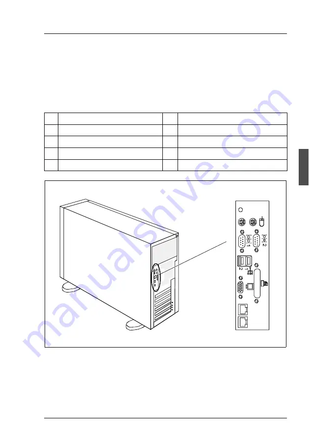
Connecting Devices to Server
The ports for external devices are on the rear of the server. Which additional
ports are available on your server depends on the PCI boards installed.
The standard ports (figure 19) are marked with symbols, and some are color-
coded.
Figure 19: Floorstand model: ports
1 Mouse port (PS/2) (green)
5
Monitor port (VGA) (blue)
2 Serial port COM2 (turquoise)
6
USB port 1 and 2 (black)
3 Optional parallel port (burgundy)
7
Serial port COM1 (turquoise)
4 LAN ports
8
Keyboard port (PS/2) (purple)
9
Global Error and ID indicators
9
1
2
3
8
7
6
5
4