background image

RX600 S5

Options Guide

61

Expansion cards and BBU

Installing expansion cards

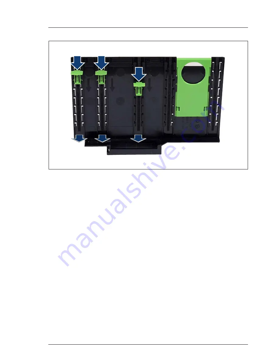
Figure 38: Removing engaging hooks from the removal tool

Ê

Push the green engaging hooks down in the direction of the arrows (1) until 
they disengage from the removal tool.

Ê

Remove the engaging hooks (2) and keep them in a safe place.

/

/

/

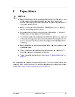
0

0

0

Содержание PRIMERGY RX600 S5

Страница 1: ...Options Guide English PRIMERGY RX600 S5 Server Options Guide August 2012 ...

Страница 2: ...mentation mbH 2010 Pfad C Programme FCT tim_app tim_local work PICHOL OBJ_DOKU 4867 001 fm Copyright 2010 Fujitsu Technology_Solutions GmbH All rights reserved Delivery subject to availability right of technical modifications reserved All hardware and software names used are trademarks of their respective manufacturers The contents of this manual may be revised without prior notice Fujitsu assumes...

Страница 3: ...semblies and in the mouse and keyboard are limited life components Use of these components beyond their operating life may result in electrolyte leakage or depletion potentially causing emission of foul odor or smoke As a guideline in a normal office environment 25 C operating life is not expected to be reached within the maintenance support period 5 years However operating life may be reached mor...

Страница 4: ... follows the guidelines of Voltage Dip Immunity of Personal Computer issued by JEITA the Japan Electronics and Information Technology Industries Association Technology controlled by the Foreign Exchange and Foreign Trade Control Law of Japan Documents produced by Fujitsu may contain technology controlled by the Foreign Exchange and Foreign Trade Control Law of Japan Documents which contain such te...

Страница 5: ...tions Guide Only for the Japanese market I Although described in this manual some sections do not apply to the Japanese market These options and routines include USB Flash Module UFM Replacing the lithium battery ...

Страница 6: ...OptionsGuide RX600 S5 cognitas Gesellschft für Technik Dokumentation mbH 2010 Pfad C Programme FCT tim_app tim_local work PICHOL OBJ_DOKU 4867 001 fm ...

Страница 7: ...dure 13 3 Safety instructions 15 4 Preparation 21 4 1 Opening the server 22 5 Main memory 25 5 1 Population rules 26 5 2 Expanding the main memory 28 5 2 1 Filling empty slots of a populated board 28 5 2 2 Installing an additional memory board 31 6 Processors 33 6 1 Installing additional processors 33 6 2 Replacing a processor 41 6 3 Replacing the heat sink 45 7 Tape drives 47 ...

Страница 8: ...module frame 48 7 2 Installing the tape drive 50 7 3 Cabling the tape drive 52 7 3 1 Cabling the USB tape drive 53 7 3 2 Cabling the SAS tape drive 55 8 Expansion cards and BBU 57 8 1 Installing expansion cards 58 8 2 Installing a BBU 63 9 Further options 69 9 1 TPM Trusted Platform Module 69 9 2 UFM USB Flash Module 72 10 Completion 75 11 Appendix 79 11 1 Cabling 79 Index 81 ...

Страница 9: ...ent ServerView Suite Prefailure Detection and Analysis PDA and Automatic Server Reconfiguration and Restart ASR R Security functions in the BIOS setup and on the system board protect the data on the server against manipulation Additional security is provided by the lockable rack door The server is used exclusively as a rack model It offers a whole host of configuration options but only uses four h...

Страница 10: ... PRIMERGY RX600 S5 Server Operating Manual PRIMERGY RX600 S5 Server Options Guide System Board D2870 for PRIMERGY RX600 S5 Technical Manual D2870 BIOS Setup Utility for PRIMERGY RX600 S5 manual I PRIMERGY manuals are available in PDF format on the ServerView Suite DVD 2 The ServerView Suite DVD 2 is part of the ServerView Suite supplied with every server If you no longer have the ServerView Suite ...

Страница 11: ...ry modules This allows a maximum memory capacity of 1024 GB as soon as 16 GB memory modules are available Processors The system board can be upgraded to include up to four processors You may only use processors of the same type all processors must have the same frequency and cache size Accessible drives You can add a CD DVD BD drive in 0 5x5 25 inch format and a tape drive in 5 25x1 6 inch format ...

Страница 12: ... a TPM Trusted Platform Module This module enables programs from third party manufacturers to store key information USB Flash Module UFM The server can be fitted with two USB Flash Modules UFM These modules can be used as optional memory for embedded software solutions e g VMware or as a software dongle 1 4 Notational conventions The following notational conventions are used in this manual Text in...

Страница 13: ...plug all power cords from the power outlet Failure to do so can cause electric shock Ê First of all carefully read the safety instructions in the chapter Safety instructions on page 15 Ê Make sure that all necessary manuals see the section Documentation overview on page 10 are available print the PDF files if required Most importantly you will need the Operating Manual for the server and the Techn...

Страница 14: ...echnik Dokumentation mbH 2010 Pfad C Programme FCT tim_app tim_local work PICHOL OBJ_DOKU 4870 001 fm I For the latest information on optional products provided for the RX600 S5 see the configurator of this server https sp ts fujitsu com dmsp docs cnfgrx600s5 pdf ...

Страница 15: ...er from all liability Any failure to observe the guidelines in this manual and any improper repairs could expose the user to risks electric shock energy hazards fire hazards or damage the equipment Before installing removing internal options to from the server turn off the server all peripheral devices and any other connected devices Also unplug all power cords from the power outlet Failure to do ...

Страница 16: ... power plug from the safety socket Always connect the device and the attached peripherals to the same power circuit Otherwise you run the risk of losing data if for example the server is still operating but the peripheral device e g storage subsystem has failed during a power outage Take notice that the data cables to peripheral devices are adequately shielded To the LAN wiring the requirements ap...

Страница 17: ...egulations and regulations governing RFI suppression Information on which system expansions are suitable can be obtained from the customer service centre or your sales outlet The components or parts marked with a warning label e g lightning symbol may only be opened removed or exchanged by authorized qualified personnel The warranty expires if the device is damaged during the installation or repla...

Страница 18: ...DVD BD fragments can pierce the cover of the optical drive equipment damage and can fly out of the device danger of injury particularly to uncovered body parts such as the face or neck High humidity and airborne dust levels are to be avoided Electric shocks and or server failures may be caused by liquids such as water or metallic items such as paper clips entering a drive Shocks and vibrations are...

Страница 19: ...the CD DVD BD with a soft dry cloth then let it air dry Do not dry the CD DVD BD using devices such as a hair dryer To avoid dust damage and deformation keep the CD DVD BD in its case whenever it is not in use Do not store CDs DVDs BDs at high temperatures Areas exposed to prolonged direct sunlight or near heating appliances are to be avoided I You can prevent damage from the optical drive and the...

Страница 20: ...er plug before installing or removing components containing ESDs You must always discharge yourself of static charges e g by touching a grounded object before working The equipment and tools you use must be free of static charges Only touch the components at the positions highlighted in green touch points Do not touch any exposed pins or conductors on a component Use a grounding cable designed for...

Страница 21: ...ti tilt plate may cause the rack to tip over Be careful not to pinch fingers or clothes when sliding out the server or pushing it back Failure to do so may cause injury Before attaching the cover make sure no unnecessary parts or tools are left inside the server Before turning on the server make sure the cover is closed Follow the safety instructions in the chapter Safety instructions on page 15 Ê...

Страница 22: ...OKU 4872 001 fm 4 1 Opening the server Pulling the server out of the rack and opening the server Figure 2 Removing the server Ê Loosen the two knurled screws 1 and pull the server carefully out of the rack as far as possible 2 V CAUTION Do not use the pulled out server as a surface on which to put things or as a work surface especially do not lean on or against it 0 0 ...

Страница 23: ...rver Figure 3 Removing the housing cover Ê Remove the little screw see circle in figure above and put it in a safe place Ê Push the two green touchpoints on the cover and move the cover backward by approximately 2 centimeters Ê Lift off the housing cover ...

Страница 24: ...24 OptionsGuide RX600 S5 Opening the server Preparation cognitas Gesellschft für Technik Dokumentation mbH 2010 Pfad C Programme FCT tim_app tim_local work PICHOL OBJ_DOKU 4872 001 fm ...

Страница 25: ...efore installing or removing memory modules otherwise you may suffer burns When installing or removing memory modules make sure you remove the screws at the specified points only to avoid injury or equipment failure Ê Do not insert and remove memory modules repeatedly as this may cause equipment failure Ê If a memory module has not been correctly installed it may cause a fire Make sure you insert ...

Страница 26: ...is shown in figure 4 5 1 Population rules The minimum required for booting the system is two DIMMs Memory boards must be fitted with DIMMs in lockstep pairs see figure 6 Both DIMMs of a pair must have identical values I This rule always applies Therefore memory boards must be fitted with DIMMs as follows 1 Start with DIMM slots 1B and 1D minimum per memory board 2 Now fill DIMM slots 1A and 1C 3 C...

Страница 27: ...xes Each memory board comes with two memory buffers on board so called BOBs Each BOB controls two memory channels e g A B or C D For performance reasons two channels of different BOBs are used in parallel to access the DIMMs The DIMMS that are locked together like this as pairs are called lockstep pairs FNPSZ NPEVMFT T FNPSZ NPEVMFT T FNPSZ DPOUSM CPY FNPSZ DPOUSM CPY 0 PDLTUFQ QBJS PDLTUFQ QBJS P...

Страница 28: ...ys to expand the main memory Filling the empty slots of an already populated board Installing an additional memory board see page 31 5 2 1 Filling empty slots of a populated board Figure 7 Button and indicators on memory board Ê Press the ATTN button 1 of the relevant memory board Ê Wait until ATTN LED 2 and Power LED 3 are turned off 1 ATTN button 4 MIRROR LED green 2 ATTN LED orange 5 8x DIMM fa...

Страница 29: ...e memory board Ê Locate the slots according to the population rules and the slot assignment described in figure 4 on page 26 Figure 9 Removing a memory module Ê Press the securing clips on both sides of the relevant memory slot outward 1 Ê If the slot was filled pull the memory module out of the slot 2 0 0 0 ...

Страница 30: ...il the securing clips on both sides of it engage 2 Reinstalling the memory board Figure 11 Installing a memory board Ê Slide the memory board down 1 in the lateral guide channels until it stops Swivel the levers in the direction of the arrows 2 Ê Make sure that the green locks on the top engage Ê Press the ATTN button Ê Wait until the ATTN LED is turned off Ê Close the server connect it to the pow...

Страница 31: ...pulated board on page 28 Ê Remove the air baffle of the unused memory board slot Figure 12 Removing the air baffle of an unused memory board slot Ê Press on the top of the memory air baffle 1 move it in the direction of the arrow 2 and out of the housing V CAUTION Unused memory board slots must have an air baffle installed to ensure system cooling I Keep the memory air baffle for future use 0 ...

Страница 32: ...ure 13 Installing a memory board Ê Slide the memory board down 1 in the lateral guide channels until it stops Swivel the levers in the direction of the arrows 2 Ê Make sure that the green locks on the top engage Ê Press the ATTN button Ê Wait until the ATTN LED is turned off Ê Close the server connect it to the power outlet and switch it on as described in the chapter Completion on page 75 0 0 ...

Страница 33: ... When installing the processor be careful not to bend the pins of the processor socket Follow the safety instructions in the chapter Safety instructions on page 15 6 1 Installing additional processors The system board can be upgraded to include up to four processors V CAUTION Only processors of the same type may be used on the system board That means the number of the internal processor cores as w...

Страница 34: ...lschft für Technik Dokumentation mbH 2010 Pfad C Programme FCT tim_app tim_local work PICHOL OBJ_DOKU 4874 001 fm Removing the mid brace Figure 14 Location of the screws holding the mid brace Ê Loosen the six screws see circles in figure above and lift the mid brace out of the housing ...

Страница 35: ...ening the socket lever I Because the 2nd CPU has to be installed in the socket of CPU 3 for technical reasons the 3rd CPU has to be installed in the socket of CPU 2 Ê Release the socket lever see oval in figure above by pressing it sideways then lift it up as far as it will go 1 0 2 ...

Страница 36: ...ditional processors Processors cognitas Gesellschft für Technik Dokumentation mbH 2010 Pfad C Programme FCT tim_app tim_local work PICHOL OBJ_DOKU 4874 001 fm Figure 16 Removing the socket cover Ê Carefully remove the socket cover see arrow ...

Страница 37: ...ponding markings on the socket To avoid damaging the pins do not force the processor into the socket Never touch the underside of the processor Even light contaminants such as oil from human skin can destroy the processor or impair its functionality Ê Position the new processor above the socket and place it carefully into the socket Ê Lock the processor into place in the socket by pushing the sock...

Страница 38: ...stall a processor without a heat sink as the processor may overheat causing itself and the entire system board to fail Figure 18 Positioning the threaded bolts Ê Carefully place the heat sink onto the processor V CAUTION Make sure that the threaded bolts of the heat sink fit perfectly into the threaded holes otherwise the system board may be damaged I Make sure you do not touch or damage the therm...

Страница 39: ...asten the heat sink with its two screws as follows 1 Fasten both screws alternately for temporary tightening 2 Fasten both screws alternately until they are fully tightened Torque 0 6 Nm V CAUTION Be careful not to interfere with the neighboring heat sink or chassis wall Ê Reinstall the mid brace see page 34 ...

Страница 40: ... Ê Reinstall the memory dividers into the correct metal retention guides see upper line of ovals in figure above not into the black plastic guides for the memory boards I Make sure that the memory dividers snap into the memory rug supports plastic openings on the memory rug see lower line of ovals in figure above Ê Reinstall the memory boards see figure 11 on page 30 Ê Close the server connect it ...

Страница 41: ...mary clock and the FSB frequency have to be the same For multi processor operation use a suitable multiprocessor operating system Ê Open the server as described in the chapter Preparation on page 21 Ê Remove the memory boards see figure 8 on page 29 Ê Remove the mid brace see page 34 Removing the heat sink Figure 21 Removing the heat sink Ê Loosen the screws of the relevant heat sink alternately u...

Страница 42: ...nd forth to loosen it Ê Lift the heat sink out to remove it Ê Remove the residual thermal paste from the underside of the heat sink Ê Clean the underside of the heat sink using a lint free cloth Removing the processor Ê Release the socket lever by pressing it sideways and lift it up as far as it will go see figure 15 on page 35 Figure 22 Removing the old processor Ê Lift the installed processor ca...

Страница 43: ... corresponding markings on the socket To avoid damaging the pins do not force the processor into the socket Never touch the underside of the processor Even light contaminants such as oil from human skin can destroy the processor or impair its functionality Ê Position the new processor above the socket and then place it carefully into the socket Ê Lock the processor into place in the socket by push...

Страница 44: ... is spread thinly and evenly Refer to the instruction sheet supplied with the thermal paste Installing the heat sink Ê Carefully place the heat sink onto the processor see figure 18 on page 38 Figure 24 Fastening the heat sink Ê Fasten the heat sink with its two screws as follows 1 Fasten both screws alternately for temporary tightening 2 Fasten both screws alternately until they are fully tighten...

Страница 45: ...he memory boards see figure 8 on page 29 and the memory dividers Ê Remove the mid brace as described on page 34 Ê Remove the old heat sink as described on page 41 Ê Remove the residual thermal paste from the processor Ê Clean the upperside of the processor using a lint free cloth Ê Install the new heat sink as described on page 38 Ê Reinstall the mid brace see figure 14 on page 34 Ê Reinstall the ...

Страница 46: ...46 OptionsGuide RX600 S5 Replacing the heat sink Processors cognitas Gesellschft für Technik Dokumentation mbH 2010 Pfad C Programme FCT tim_app tim_local work PICHOL OBJ_DOKU 4874 001 fm ...

Страница 47: ...t boards and soldered parts of internal options are exposed and can be damaged by static electricity Before handling them first touch a metal part on the server to discharge static electricity from your body Before installing an internal accessible drive see the manual for the accessible drive When inserting an accessible drive into a server be careful not to pinch the cable etc connected to the d...

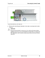
Страница 48: ...The tape drive can be installed in the relevant drive bay on the front of the server As long as no device is installed the drive bay contains a module frame with two rails needed for tape mounting Ê Open the server as described in the chapter Preparation on page 21 Figure 25 Removing the module frame Ê Press the two green touchpoints spring clips of the module frame see arrows and pull the module ...

Страница 49: ...move the two sliding rails attached to the sides by undoing the 3 screws on each V CAUTION Keep the module frame for future use If you remove the drive without installing a new one you must reinstall the module frame to comply with EMC regulations and to satisfy cooling requirements and fire protection measures ...

Страница 50: ... 27 Fastening the sliding rails to the drive Ê Fasten the two sliding rails on both sides of the drive to be installed using two screws for each Figure 28 Inserting the tape drive Ê Push the tape drive into the empty bay until it snaps into place I Make sure the tape drive has completely snapped into place When inserting the tape drive make sure you do not damage or accidently disconnect the cable...

Страница 51: ...the mounting area Carefully bend the cables as shown in figure 29 Figure 29 Bending the cables when mounting large tape drives Instructions about cabling a USB tape drive can be found in section Cabling the USB tape drive on page 53 Instructions about cabling a SAS tape drive you will find in section Cabling the SAS tape drive on page 55 ...

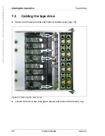
Страница 52: ...chnik Dokumentation mbH 2010 Pfad C Programme FCT tim_app tim_local work PICHOL OBJ_DOKU 4875 001 fm 7 3 Cabling the tape drive Ê Remove all memory boards and memory dividers see page 29 Figure 30 Removing the memory rug Ê Loosen the four screws see figure above and remove the memory rug ...

Страница 53: ...ns Guide 53 Tape drives Cabling the tape drive 7 3 1 Cabling the USB tape drive Figure 31 Connecting cables to the USB tape drive Ê Connect the USB data cable 1 to the drive Ê Connect the power cable 2 to the drive 0 ...

Страница 54: ...from the tape to the USB connector Ê Route the data cable as shown in figure 32 Ê Connect the other end of the data cable to an unused USB connector on the system board see circle in figure above Ê Reinstall the memory rug see figure 30 on page 52 Ê Reinstall all memory boards and memory dividers Ê Close the server connect it to the power outlet and switch it on as described in the chapter Complet...

Страница 55: ...ions Guide 55 Tape drives Cabling the tape drive 7 3 2 Cabling the SAS tape drive Figure 33 Connecting cables to the SAS tape drive Ê Connect the data cable 1 to the drive Ê Connect the power cable 2 to the drive 0 ...

Страница 56: ... cable starting from the tape drive in accordance with the plotted course see figure above in the cable channel in the side wall of the housing excess cable can be routed in a cable loop Ê Plug the SAS data cable to the SAS port on the controller Ê Reinstall the memory rug see figure 30 on page 52 Ê Reinstall all memory boards and memory dividers Ê Close the server connect it to the power outlet a...

Страница 57: ... Failure to do so can cause electric shock The circuit boards and soldered parts of internal options are exposed and can be damaged by static electricity Before handling them first touch a metal part on the server to discharge static electricity from your body Do not touch the circuitry on boards and soldered parts Hold the metallic areas or the edge of the circuit boards Follow the safety instruc...

Страница 58: ...nstall hot plug expansion cards is described in the operating manual Figure 35 Overview of all PCI Express slots Item Slot Description 1 10 PCI Express 1 0 x4 1 2 length x8 connector 2 9 PCI Express 1 0 x4 1 2 length x8 connector 3 8 PCI Express 2 0 x4 3 4 length x8 connector 4 7 hot plug PCI Express 2 0 x8 3 4 length x8 connector 5 6 hot plug PCI Express 2 0 x8 3 4 length x8 connector 6 5 PCI Exp...

Страница 59: ...n card Ê Open the expansion card lock 1 by lifting it up Ê Hold the removal tool by the green handle 2 and pull it out of the PCI slot 9 2 PCI Express 2 0 x8 3 4 length x8 connector 10 1 PCI Express 2 0 x8 3 4 length x8 connector 11 PCI Express 1 0 x1 PCIe type connector dedicated for I O riser card 12 PCI Express 2 0 x8 x8 connector dedicated for SAS controller card Item Slot Description 0 ...

Страница 60: ...moval tool pay particular attention to the engaging hooks that hold it in place Never lift these engaging hooks more than approximately 1 mm i e only lift them far enough to release the retaining plate Otherwise you could damage the engaging hooks Figure 37 Removing the retaining plate from the removal tool Ê Lift the green engaging hooks see arrows no more than approximately 1 mm until the retain...

Страница 61: ...lling expansion cards Figure 38 Removing engaging hooks from the removal tool Ê Push the green engaging hooks down in the direction of the arrows 1 until they disengage from the removal tool Ê Remove the engaging hooks 2 and keep them in a safe place 0 0 0 ...

Страница 62: ...e green engaging hooks see circles in figure above in the rods and push them down until they engage with the upper edge of the expansion card I Make sure that e g the ports on the expansion card are not blocked by the engaging hooks Installing the expansion card Ê Insert the expansion card fastened to the removal tool in the desired PCI slot Ê Close the slot lock see figure 36 on page 59 by foldin...

Страница 63: ...ow the safety instructions in the chapter Safety instructions on page 15 The Battery Backup Unit BBU backs up the memory contents of the SAS SATA RAID controller in the event of a power failure A maximum of two BBUs can be installed for each system The mounting locations within the server are shown in figure 40 Figure 40 Mounting locations of the BBU holders 1 and 2 2 1 ...

Страница 64: ...s of the battery 1 and a dedicated BBU cable 2 Figure 42 Connecting the BBU cable to the battery Ê Connect the BBU cable 1 to the connector 2 on the battery I Because the cable plug is coded it cannot be stuck in the port in a wrong way 0 0 Installing a BBU Expansion cards and BBU ...

Страница 65: ...dy installed on the side panel of the chassis The two clips see circles on the bottom edge of the holder ensure that the battery fits tightly I The battery holder 2 is located directly opposite on the other side of the server see figure 40 on page 63 The installation of the second battery is done in the same manner but rotated by 180 The cable routing for the second battery is shown in figure 47 o...

Страница 66: ...e battery in the holder 1 Ê Place the battery in the battery holder 1 as follows 1 Insert the battery at a slight angle behind the two clips see circles in picture 43 on page 65 2 Carefully press the battery into the holder until it engages under the two locking hooks see arrows in figure 44 Figure 45 Routing of the BBU cable 1 Ê Route the BBU cable through the cable guide in the side panel of the...

Страница 67: ... removing or installing the processor cover mid brace or heat sinks Figure 46 Connecting the BBU cable to the controller Ê Plug the BBU cable into the BBU connector see arrow of the SAS controller card Ê Close the server connect it to the power outlet and switch it on as described in the chapter Completion on page 9 Expansion cards and BBU ...

Страница 68: ...tim_local work PICHOL OBJ_DOKU 4876 001 fm Routing the cable of the second battery Figure 47 Routing of the BBU cable 2 Ê Route the BBU cable in the cable guide in the side panel of the housing see figure above Excess cable can be routed in a cable loop Ê Plug the connector of the BBU cable in the connector of the controller see circle in figure above ...

Страница 69: ...storage of key information e g drive encryption with Windows BitLocker Drive Encryption Figure 48 TPM installation kit Ê Open the server as described in the chapter Preparation on page 21 Ê Remove all cables USB SAS cables etc the I O riser board and the SAS controller card from the installation area see figure 49 on page 70 1 TPM Trusted Platform Module 3 Special screw for TPM 2 TPM spacer 4 TPM ...

Страница 70: ...t für Technik Dokumentation mbH 2010 Pfad C Programme FCT tim_app tim_local work PICHOL OBJ_DOKU 4877 001 fm Figure 49 Inserting the TPM spacer Ê Insert the TPM spacer into the relevant hole on the system board see arrow I Make sure that the TPM spacer engages properly on the system board ...

Страница 71: ... also figure 48 to tighten the special screw I Fasten the screw with a torque value of 0 6 Nm recommended value Ê Reinstall all previously removed cables Ê Reinstall the I O riser board and the SAS controller card Ê Close the server connect it to the power outlet and switch it on as described in the chapter Completion on page 75 I For information on configuring the TPM please see the D2870 BIOS Se...

Страница 72: ...fm 9 2 UFM USB Flash Module The server can be fitted with up to two USB Flash Modules UFM Figure 51 UFM installation kit Ê Open the server as described in the chapter Preparation on page 21 Ê Remove the I O riser board if necessary Ê Remove expansion cards if necessary for a description see the operating manual for this server 1 USB Flash Module UFM 3 UFM spacer 2 UFM nylon screw 0 1 2 ...

Страница 73: ...USB Flash Module Figure 52 Installation locations for the UFMs The first UFM must be installed in position 1 see figure above Figure 53 Mounting the UFM Ê Connect the UFM to the system board The spacer must click into the hole on the system board 0 ...

Страница 74: ...r options cognitas Gesellschft für Technik Dokumentation mbH 2010 Pfad C Programme FCT tim_app tim_local work PICHOL OBJ_DOKU 4877 001 fm Ê Close the server connect it to the power outlet and switch it on as described in the chapter Completion on page 75 ...

Страница 75: ...ely 2 cm at the back see circle in figure above Ê Push the housing cover in the direction of the arrow until it engages Ê Fasten the little screw on the cover see figure 3 on page 23 If you have not removed the server from the rack cabinet please skip steps 1 4 on the next page V CAUTION At least two people are required to install the server in the rack cabinet Do not use the handles on the rack f...

Страница 76: ...0 Pfad C Programme FCT tim_app tim_local work PICHOL OBJ_DOKU 4878 001 fm Figure 55 Inserting the server a Figure 56 Inserting the server b Ê Fully extend the telescopic rails toward the front 1 I The telescopic rails must click into place so that they can no longer be moved 0 1 2 3 4 4 5 5 ...

Страница 77: ...4 engages Ê Push up the locking mechanism of both telescopic rails 5 Ê Push the server into the rack as far as it will go 6 Ê Fasten the server to the rack 7 using the two knurled screws front panel Ê Connect all cables on the rear of the server Ê Connect all power plugs to the power outlets Ê Press the on off button to start up the server ...

Страница 78: ...78 OptionsGuide RX600 S5 Completion cognitas Gesellschft für Technik Dokumentation mbH 2010 Pfad C Programme FCT tim_app tim_local work PICHOL OBJ_DOKU 4878 001 fm ...

Страница 79: ...RX600 S5 Options Guide 79 11 Appendix 11 1 Cabling A cabling plan can be found on the next page ...

Страница 80: ...CPU 4 SATA Hot Swap Backplane alternatively 3 A3C401 13 975 A3C401 13 976 A3C401 13 977 A3C401 13 992 A3C401 13 979 A3C401 13 981 A3C401 13 983 A3C401 13 984 A3C401 13 985 A3C401 13 986 on I O riser board to optical drive to SATA HDD A3C401 13 975 A3C401 13 995 A3C401 13 994 A3C401 13 993 A3C401 13 987 A3C401 13 987 T26139 Y3969 V101 A3C401 13 981 A3C401 13 982 A3C401 13 985 iBBU A3C401 13 980 T26...

Страница 81: ...sitive to electrostatic discharge 20 expansion cards install 58 F features 9 H heat sink fastening 39 installing 38 removing 41 housing cover removing 23 I information additional 11 inserting processor 37 install expansion cards 58 installation kit UFM 72 installing BBU 63 heat sink 38 memory board 30 memory module 30 tape drive 50 TPM 71 Trusted Platform Module 71 UFM 73 USB flash module 73 L las...

Страница 82: ...y additional 12 processor adding 11 33 inserting 37 installation rules 33 replacing 41 R removing air baffle 31 heat sink 41 housing cover 23 memory board 29 memory module 29 mid brace 34 module frame 48 replacing processor 41 retaining plate remove 60 S SAS tape drive installing 50 server features 9 T tape drive connecting SAS drive 55 connecting USB drive 53 installing 50 SAS cable routing 56 US...

Отзывы: