Using the ServerView Operations Manager
▶
To toggle the ID indicator from the ServerView Operations Manager, choose
Single System View
and press the
Locate
button.
Using the Infrastructure Manager
▶
To toggle the ID indicator from the Infrastructure Manager, select a node
from the
Node List
screen and operate the ID indicator from the
Action
button.
4.1.3
Determining the error class
The Local Service Concept (LSC) allows you to identify defective server
components. Failure events are assigned to one of two error classes:
–
Global Error (for non CSS components) events that need to be resolved by
maintenance personnel
–
Customer Self Service (for CSS components) error events that may be
resolved by operating personnel
The Global Error indicator and the CSS indicator can be found on the front side
and the rear side of the server.
In some cases the indicator on the rear is designed as a combined
indicator (Global Error, ID and CSS indicator).
The indicators also light up in standby mode and after a server restart
due to a power failure.
▶
Check the Global Error indicator and the CSS indicator.
4.1.4
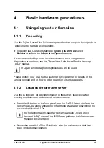
Locating the defective component
After determining the error class by the CSS indicator or the Global Error
indicator, indicators on the components and onboard indicators on the system
board allow you to identify the defective component, see
Basic hardware procedures
46
Upgrade and Maintenance Manual
RX2530 M6
Содержание PRIMERGY RX2530 M5
Страница 18: ...Content Upgrade and Maintenance Manual RX2530 M6 ...
Страница 194: ...Fans 194 Upgrade and Maintenance Manual RX2530 M6 ...
Страница 262: ...Expansion cards and backup units 262 Upgrade and Maintenance Manual RX2530 M6 ...
Страница 278: ...Main memory 278 Upgrade and Maintenance Manual RX2530 M6 ...
Страница 324: ...Accessible drives 324 Upgrade and Maintenance Manual RX2530 M6 ...
Страница 336: ...Front panel 336 Upgrade and Maintenance Manual RX2530 M6 ...
Страница 344: ...Serial interface 344 Upgrade and Maintenance Manual RX2530 M6 ...
Страница 428: ...FUJITSU Server PRIMERGY RX2530M6 Reference Manual Reference Manual English Cable plan for April 2021 ...
Страница 438: ...11 RX2530 M6 Basic OOB 4x3 5 Cable plan System Board D3890 A SMB1 4x 3 5 HDD Backplane SMB1 CA05950 2054 SB BP ...
Страница 439: ...12 RX2530 M6 Basic OOB 8x2 5 Cable plan System Board D3890 A SMB1 8x 2 5 HDD Backplane SMB1 CA05950 2054 SB BP ...
Страница 440: ...13 RX2530 M6 Basic OOB 10x2 5 Cable plan System Board D3890 A SMB1 10x 2 5 HDD Backplane SMB1 CA05950 2054 SB BP ...
Страница 444: ...17 RX2530 M6 Power 4x3 5 Cable plan CA05950 2050 System Board D3890 A PWR 2 4x3 5 HDD Backplane PWR1 ...
Страница 445: ...18 RX2530 M6 Power 8x2 5 Cable plan CA05950 2050 System Board D3890 A PWR 2 8x2 5 HDD Backplane PWR1 ...
Страница 446: ...19 RX2530 M6 Power 10x2 5 Cable plan CA05950 2052 System Board D3890 A PWR 2 10x2 5 HDD Backplane PWR1 ...
Страница 449: ...22 RX2530 M6 Power Rear 2x2 5 Cable plan System Board D3890 A PWR 1 2x2 5 rear HDD Backplane CA05950 2077 PWR 5 ...
Страница 450: ...23 RX2530 M6 Power Internal RAID Riser Cable plan CA05950 2051 System Board D3890 A PWR 1 Internal RAID Riser PWR 1 ...
Страница 478: ...51 RX2530 M6 Data Dual microSD 64GB Enterprise Cable plan Dual microSD 64GB Enterprise A ROC CON1 Y4018 V8 ...
Страница 480: ...List of all used screws for PRIMERGY Servers Assembled in Germany and Japan February 2019 ...


