14
U41290-J-Z816-3-76
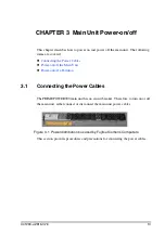
CHAPTER 3 Main Unit Power-on/off
3.1.1
Power cable connection for the PRIMEPOWER900 main unit
(model name: PW0XDRyyyx)
This section explains the power cable connection for the PRIMEPOWER900 main
unit (model name: PW0XDRyyyx).
The number of power cables required for the main unit depends on the power supply
configuration of the main unit. Three configurations for power cable connections are
described below:
l
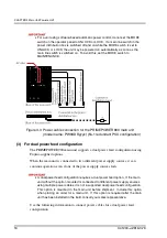
For non-redundant configuration of power supply unit (PSU)
l
For N+1 redundant configuration of power supply unit (PSU)
l
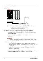
For dual power feed configuration
(1)
For non-redundant configuration of power supply unit (PSU)
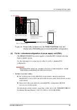
Use the following information to connect power cables for a non-redundant PSU
configuration.
• Number of power cables
Two or three power cables (IEC320) are provided for the main unit power distribution
box (one each for the main unit, the first system board, and the second system board).
For information about correctly connecting a cable, refer to the “PRIMEPOWER900
Installation Planning Manual” ( (U41297-J-Z816-x-76/C120-H013EN).
4
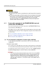
For a unit using software-based automatic power control, do not set the MODE
switch on the operator panel to UNLOCK or LOCK. If a main line switch in the
power distribution box is switched off and on while the MODE switch is set to
UNLOCK or LOCK, the unit may be powered on automatically as soon as the
main line switch is switched on. To avoid this situation, set the MODE switch to
MAINTENANCE.
Equipment damage
l
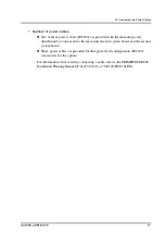
Connect each power cable to a grounded service outlet located within the operator's
reach.
l
Connect the power cables such that the capacity of the circuit breaker for the relevant
branch circuit, or the circuit breaker for the outlet box in the rack, is not exceeded.
For the branch circuit, select a circuit breaker that meets the circuit breaker
requirements specified in the “PRIMEPOWER900 Installation Planning Manual”
(U41297-J-Z816-1-76/C120-H013EN).
Содержание PRIMEPOWER900
Страница 1: ...Edition September 2004 PRIMEPOWER900 ...
Страница 8: ......
Страница 16: ......
Страница 20: ......
Страница 22: ......
Страница 30: ......
Страница 42: ......
Страница 76: ......
Страница 95: ...U41290 J Z816 3 76 65 6 2 Partition Mode Figure 6 3 Correspondence of system boards PCI slots and disks ...
Страница 104: ......
Страница 110: ......
Страница 122: ......
Страница 128: ......
Страница 130: ......
Страница 143: ...U41290 J Z816 3 76 113 C 4 PCI Hot Plug Figure C 4 Rear view of the PCI disk box showing location of PCI slots ...
Страница 166: ......
Страница 174: ......
Страница 176: ......


