Fujitsu PDS5001 Скачать руководство пользователя страница 28

26

ADJUSTING SCREEN POSITION AND SIZE (POSITION/SIZE MENU)

Press 

.

The main menu screen will appear.

Press 

 or 

 to select

“POSITION/SIZE”.

Each time you press   or  , one of the available
menus appears in the following sequence:

The POSITION/SIZE Menu screen will appear.

Press 

 or 

 to select

“Position”.

Press 

 .

The “Position” adjustment screen will appear.

Press 

 or 

 to select

“Horizontal” values of screen
position.

Press 

 .

The “Horizontal” adjustment screen will appear.

Press  

 or 

 to change

horizontal values.

: Moves screen to the right.

: Moves screen to the left.

Press 

 to store.

Press 

  when you finish.

* Repeat steps 3 to 8 when you wish to make

changes to other options.

* You can also use the

switches on the display’s
control panel to accomplish
these steps.

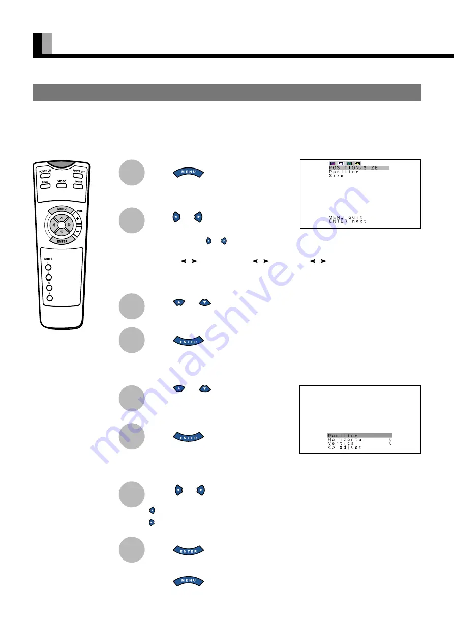
BASIC OPERATION [EX.: ADJUSTING HORIZONTAL DIRECTION OF SCREEN POSITION]

“POSITION/SIZE” selected from the main
menu screen

You can make changes to all screen adjustment options in the POSITION/SIZE Menu.

The changes you make will be stored for the selected input mode.  Therefore, you need to select a desired input mode before making any
changes.

“Position” adjustment screen

PICTURE 

 POSITION/SIZE 

 FEATURES 

 FACTORY DEFAULT

8

1

2

3

4

5

6

7

Содержание PDS5001

Страница 1: ...1U PDS5002W PDS5002U Before Use Safety Precautions 2 3 Features 4 Accessories 5 HandyTips 5 Installation 6 Usage Part Names and Functions 7 10 Using the Remote Control 11 Connecting the Display to External Equipment 12 13 Basic Operations 14 Selecting Input Mode 15 Watching Pictures on the Wide Screen 16 17 How to Use Menus 18 23 Adjustments Adjusting Pictures PICTURE Menu 24 25 Adjusting Screen P...

Страница 2: ...EN61000 4 2 1995 EN61000 4 3 1996 EN61000 4 4 1995 EN61000 4 5 1995 EN61000 4 6 1996 EN61000 4 8 1993 EN61000 4 11 1994 Safety e EN60065 By conformance with the standard referenced the product follows the provisions of the directives listed below a EC Council Directive 89 336 EEC of 3rd May 1989 b EC Council Directive 92 31 EEC of 28th April 1992 c EC Council Directive 93 68 EEC of 22nd July 1993 ...

Страница 3: ...EN61000 4 2 1995 EN61000 4 3 1996 EN61000 4 4 1995 EN61000 4 5 1995 EN61000 4 6 1996 EN61000 4 8 1993 EN61000 4 11 1994 Safety e EN60065 By conformance with the standard referenced the product follows the provisions of the directives listed below a EC Council Directive 89 336 EEC of 3rd May 1989 b EC Council Directive 92 31 EEC of 28th April 1992 c EC Council Directive 93 68 EEC of 22nd July 1993 ...

Страница 4: ...oduct may cause radio interference in which case the user may be required to take adequate measures WARNING TO REDUCE THE RISK OF FIRE AND ELECTRIC SHOCK DO NOT EXPOSE THIS PRODUCT TO RAIN OR MOISTURE IMPORTANT IMPORTANT SAFEGUARDS Electrical energy can perform many useful functions This unit has been engineered and manufactured to assure your personal safety But IMPROPER USE CAN RESULT IN POTENTI...

Страница 5: ... in a fire or electric shock Never spill liquid of any kind on the product Do not attempt to service this product yourself as opening or removing covers may expose you to dangerous voltages and other hazards Refer all service to qualified service personnel Unplug this product from the wall outlet and refer service to qualified service personnel under the following conditions a When the power suppl...

Страница 6: ...de and Zoom are also available Vertical installation The display can be installed vertically enabling advertisement to be displayed In this case you can set up the display so that on screen information such as input modes and menus is displayed properly Power management function The display features a DPMS Display Power Management Signaling function that ensures automatic power saving capability F...

Страница 7: ...en used with other audio visual equipment You may need to move your display if it produces degraded pictures or noise due to electromagnetic radiation or if the infrared remote control does not function properly Pictures may not be displayed properly if you connect a non standard PC to the RGB input terminal In this case contact your dealer for more information The protective circuit built into th...

Страница 8: ...ned between 0 C and 40 C Never attempt to tilt the display sideways or backward To prevent the power and other cables from being accidentally pulled make sure that they run along the wall or through corners The display can be installed with either of its sides facing down Note The display is a highly precise piece of equipment and therefore must be packed properly before transportation Be sure to ...

Страница 9: ...des 5 Wide screen selector button WIDE Switches the screen over to a desired wide screen 6 Menu button MENU Displays picture adjustment menus 7 Adjustment buttons The buttons can also be used to scroll through the options when a menu is displayed 8 Adjustment buttons The buttons can also be used to scroll through options in a menu or to change values 9 Enter button ENTER Press this button to final...

Страница 10: ...t terminal RGB 3 INPUT BNC Connect this terminal to the PC s display analog RGB output terminal or decoder digital broadcast tuner etc output terminal When RGB3 input terminal is connected Comp video mode is not available 6 Component video input terminal COMPONENTVIDEO INPUT Connect this terminal to the component video output color difference output terminal of your HDTV unit or DVD player When Co...

Страница 11: ...13 Horizontal synchronization 6 Ground 14 Vertical synchronization 7 Ground 15 8 Ground Frame Ground mD sub terminal RGB2 INPUT mD sub Pin No Signal 1 DCD Data Carrier Detect 2 RD Received Data 3 TD Transmit Data 4 DTR DataTerminal ready 5 GND Ground 6 DSR Data Set Ready 7 RTS RequestTo send 8 CTS ClearTo Send 9 RI Ring Indication RS 232C terminal RS 232C ...

Страница 12: ...ress this button to finalize the selection of a desired menu or option within a menu 0 Display selector buttons SHIFT 1 4 See P 34 When you use two or more displays you can use these buttons to control up to four displays by assigning a unique number to each display PUTTING BATTERIES INTHE REMOTE CONTROL Remote Control 1 To remove the cover slide it outwards while pressing it down 2 Place two AA b...

Страница 13: ...n any volatile solvent such as benzene or thinner EFFECTIVE RANGE FORTHE REMOTE CONTROL Point the remote control at the display s signal receiver when using it Make sure that there are no obstacles between the remote control and the display s signal receiver USINGTHE REMOTE CONTROL Information The remote control may not function properly if you use a high frequency fluorescent lamp If you experien...

Страница 14: ... dealer for more information CONNECTINGTHE DISPLAYTO EXTERNAL EQUIPMENT Carefully check the terminals for position and type before making any connections Loose connectors can result in picture or color problems Make sure that all connectors are securely inserted into their terminals CONNECTINGTHE DISPLAYTO EXTERNAL EQUIPMENT Terminal Connector VIDEO INPUT BNC S VIDEO INPUT S terminal COMPONENT VID...

Страница 15: ...UT RGB1 INPUT DVI D RGB2 INPUT mD sub VIDEO INPUT S VIDEO INPUT RS 232C To RS 232C output terminal To display digital RGB output terminal To S video output terminal To video output terminal To display analog RGB output terminal To color difference output terminal To display analog RGB output terminal ...

Страница 16: ...e remote control When you do so the power indicator lamp turns green Press or to select a desired input mode BASIC OPERATIONS You can also use the switches on the display s control panel to accomplish these steps TURNING ON THE POWER Press when the power is ON The power indicator lamp turns red TURNING OFF THE POWER 1 2 3 ...

Страница 17: ...so use the switches on the display s control panel to accomplish these steps VIDEO INPUT MODE RGB INPUT MODE S video mode Comp video mode Press to select a desired input mode Each time you press a different input mode appears The sequence is as follows RGB1 Displays pictures from equipment connected to the RGB1 DVI D terminal RGB2 Displays pictures from equipment connected to the RGB2 mD sub termi...

Страница 18: ...poses or for a public audience may constitute a copyright infringement For films try to select a mode having the same aspect ratio as the original picture this enables the director s original intentions to be preserved Reference See P 26 27 for how to adjust the picture size and position Press The currently selected mode will appear Press to select a desired picture mode Each time you press a diff...

Страница 19: ...ures of standard size on the wide screen Wide2 Wide Ideal for displaying vertically extended pictures such as squeezed pictures and recorded HDTV programs Auto The screen size changes automatically in accordance with the contents of image software you use Zoom1 Zoom Enlarges horizontally extended pictures equally in all directions to maintain the aspect ratio constant Zoom2 Reduces the height of h...

Страница 20: ...sily distinguish between these menus as shown below Press or to make adjustment setup and press to store Do not change input signals when any of the menus are displayed USINGTHE PICTURE MENU When you finish selecting a desired option in the PICTURE menu screen press At this time the adjustment setup screen for that option will appear You can use or to change the value for the option Press to store...

Страница 21: ...2 Dynamic3 Dynamic4 RGB Dynamic1 Dynamic2 Dynamic3 Dynamic4 Static Warm Standard Cool User 0 to 255 for each of Red Green and Blue Off Min Std Max USINGTHE POSITION SIZE MENU Option 1 Position Function Adjusts screen position Operation Range Video S video Horizontal 30 to 30 Vertical Zoom 15 to 15 Others 7 to 7 Comp video 16 to 16 1080I 720P 32 to 32 RGB PC 150 to 150 Decoder 16 to 16 1080I 720P 3...

Страница 22: ...minal Menu screen Others 1 2 Menu screen Adjustment Menu See P 28 29 Option 1 Dot Clock for RGB2 RGB3 2 Clock Phase for RGB2 RGB3 3 Vertical Sync for RGB2 RGB3 4 Clamp Position for Comp video RGB2 RGB3 5 Auto Calibration for RGB2 RGB3 Function Adjusts the dot clock Adjusts clock phase Corrects vertical synchronization signal Adjusts clamp pulse phase Selects the optimum dynamic range of images Ope...

Страница 23: ...displayed English Deutsch German Español Spanish Français French Italiano Italian Português Portuguese Option 1 Video Input for Video 2 S video Input for S video 3 BNC Input 4 D SUB Input InputTerminal Menu See P 28 31 32 Function Selects video mode Selects video mode Selects BNC Input signal Selects D SUB Input signal Operation Use or for switching Use or for switching Display BNC Input screen an...

Страница 24: ...Press to store Display the Screen Orbiter adjustment screen and use or to select an option Use or to switch between available choices for the selected option Use or for switching Use or for switching Use or for switching Display Code Setting screen and press or to select an option Select Manual to set up Parameter Use or for switching Use or for switching Use or for switching Use or for switching ...

Страница 25: ...nt setting made in the MENU to factory settings See P 36 FACTORY DEFAULT Menu screen Yes No selection screen Option FACTORY DEFAULT Function Restores the adjustment setting made in the MENU to factory settings Operation Select Execute and Yes and press to restore factory settings Range Yes No ...

Страница 26: ...isplay s control panel to accomplish these steps BASIC OPERATIONS EX ADJUSTINGTINT Tint PICTURE selected in the main menu screen Tint selected in the PICTURE Menu screen Video Input Mode You can make changes to all picture adjustment options in the PICTURE Menu The changes you make will be stored for a selected input mode Therefore you need to select a desired input mode before making any changes ...

Страница 27: ...on picture Use either of better picture quality Static Suitable for watching a still picture Press to store Can select Static only in RGB mode Adjusting ColorTemperature ColorTemp Use or to specify a desired color temperature Each time you press or one of the available choices appears in the following sequence Warm More reddish colors Standard Standard color temperature Cool More bluish colors Use...

Страница 28: ...ues Moves screen to the right Moves screen to the left Press to store Press when you finish Repeat steps 3 to 8 when you wish to make changes to other options You can also use the switches on the display s control panel to accomplish these steps BASIC OPERATION EX ADJUSTING HORIZONTAL DIRECTION OF SCREEN POSITION POSITION SIZE selected from the main menu screen You can make changes to all screen a...

Страница 29: ...Comp video mode RGB mode Adjusting Screen Position Position Horizontal position Horizontal Moves screen to the right Moves screen to the left Vertical position Vertical Moves screen up Moves screen down Press to store Adjusting Screen Size Size Screen width Width Increases width Reduces width Screen height Height Increases height Reduces height Press to store You cannot adjust screen size in RGB1 ...

Страница 30: ...rs Press or to select Language Press The Language selection screen will appear Press or to select the language Press The menu is displayed in the selected language Press when you finish Repeat steps 3 to 8 when you wish to make changes to other options 1 2 You can also use the switches on the display s control panel to accomplish these steps BASIC OPERATION EX SELECTING LANGUAGE Language FEATURES ...

Страница 31: ...Use or to specify a value between 1 and 32 Press to store Eliminating Flicker Vertical Sync Corrects the vertical synchronization signal timing to eliminate vertical flicker Use or to specify a value between 1 and 1 Press to store Some type of signal can not be selected Adjusting Clamp Position Clamp Position Adjusts clamp pulse in accordance with the input signal received from connected equipment...

Страница 32: ...ano Italian Português Portuguese 3 Press The menu is displayed in the selected language OTHERADJUSTMENTS FEATURES MENU Continued Displaying the optimum movie pictures 24 Frame Mode Can make the optimum display of 24 frames second signals such as movie pictures Each time you press or one of the available choices appears in the following sequence On Off On Displays the optimum movie pictures Off Dis...

Страница 33: ... to BNC Input terminal 1 Select BNC Input and press BNC Input screen appears 2 Select the signal system to receive Each time you press or one of the available choices appears in the following sequence Comp video For using color difference input RGB PC For using PC wih RGB signal input Decoder For using decoder with RGB signal input 3 Press or to select Function 4 Select Comp video or Decoder by FU...

Страница 34: ...d of time When DPMS is active the power indicator lamp turns orange 1 Select DPMS and press DPMS screen appears 2 Press or to select Time 3 Each time you press or one of the available choices appears in the following sequence Off Disables DPMS Number Approximate time before DPMS starts Unit minutes The power indicator lamp turns orange while the DPMS is ON The power turns ON automatically when the...

Страница 35: ...ority Input Priority All modes You can use this option to switch between modes only when a signal is received through the selected input mode terminal You cannot switch the input mode Each time you press or one of the available choices appears in the following sequence Off Switches between modes normally Other modes Displays pictures when a signal is received through the selected input mode termin...

Страница 36: ... each signal Press to store In Auto mode the resolution of VGA WVGA 480P XGA WXGA SXGA and SXGA may not be automatically distinguished Switch to the fixed display when the image is not displayed properly Specifying RGB Input Signal Code Setting You can use this option to specify and display the type of RGB input signal by code number Each time you press or one of the available choices appears in t...

Страница 37: ...on Each time you press or one of the available choices appears in the following sequence 90 Deg Displays text from left to right when the display is installed with the power indicator lamp at the top Normal Displays text normally 90 Deg Displays text from left to right when the display is installed with the power indicator lamp at the bottom Press to store Be sure to make this setup when changing ...

Страница 38: ...ing completed the initialization will be displayed after initializing Press when you finish 1 2 You can also use the switches on the display s control panel to accomplish these steps FACTORY DEFAULT selected in the main menu screen Displays the message of whether to proceed the initialization 3 4 5 Displays the message of having completed the initialization You can restore the values of the adjust...

Страница 39: ... options do not match the display colors perfectly Warning To prevent injury fire and electric shock arrange for options to be initially installed or installed at a different location by your dealer The pipe is not supplied with the ceiling hanging unit so consult your produce dealer CAUTION This display PDS5001W PDS5001U PDS5002W PDS5002U is for use only with Fujitsu General Limited s option P 50...

Страница 40: ...l Vertical frequency Hz Main corresponding signals Video S video mode 852 x 480 31 72 59 97 640 x 480 31 47 59 94 VGA 640 x 480 37 86 72 81 VGA 72 Hz 640 x 480 37 50 75 00 VGA 75 Hz 640 x 480 43 27 85 01 VGA 85 Hz 720 x 400 31 47 70 09 400 lines 800 x 600 37 88 60 32 SVGA 60 Hz 800 x 600 48 08 72 19 SVGA 72 Hz 800 x 600 46 88 75 00 SVGA 75 Hz 800 x 600 53 67 85 06 SVGA 85 Hz 1024 x 768 48 36 60 00...

Страница 41: ...7 Vp p 75 Ω Applicable systems NTSC PAL SECAM PAL60 N PAL M PAL 4 43NTSC PC input terminal RGB1 input terminal 1 DVI D terminal RGB2 input terminal mD sub 3 rows 15 pin Picture signal 0 7 Vp p 75 Ω Synchronization signal TTL level RGB3 input terminal 5 BNC terminals R 0 7 Vp p 75 Ω G 0 7 Vp p 75 Ω B 0 7 Vp p 75 Ω H TTL level or 0 3 Vp p 75 Ω V TTL level or 0 3 Vp p 75 Ω Control terminal 1 RS 232C ...

Страница 42: ...equency of other than 48 3 51 8 or 58 4 61 4 Hz Change the setting of your PC etc Remove the power plug from the receptacle and inform your dealer about how the lamp flashed As explained below the power indicator lamp flashes differently depending on the type of problem Flashes repeatedly Improper supply voltage level Flashes once Malfunction by the fan Flashes twice Excessive temperature Flashes ...

Страница 43: ...1116 Suenaga Takatsu ku Kawasaki 213 8502 Japan Printed in Japan 8112380027 ...

Отзывы: