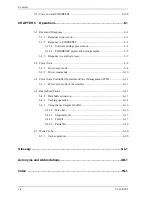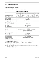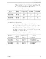
Contents
x
C141-E224
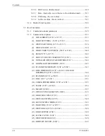
CHAPTER 2
Device Configuration ................................................................ 2-1
2.1 Device Configuration ........................................................................................2-2
2.2 System Configuration........................................................................................2-3
2.2.1
SATA interface .....................................................................................2-3
2.2.2
Drive connection ...................................................................................2-3
CHAPTER 3
Installation Conditions.............................................................. 3-1
3.1 Dimensions........................................................................................................3-2
3.2 Mounting ...........................................................................................................3-3
3.3 Connections with Host System .........................................................................3-9
3.3.1
Device connector...................................................................................3-9
3.3.2
Signal segment and power supply segment ........................................3-10
3.3.3
Connector specifications for host system ...........................................3-10
3.3.4
SATA interface cable connection .......................................................3-11
3.3.5
Note about SATA interface cable connection ....................................3-11
CHAPTER 4
Theory of Device Operation...................................................... 4-1
4.1 Outline ................................................................................................................4-2
4.2 Subassemblies ....................................................................................................4-2
4.2.1 Disk .........................................................................................................4-2
4.2.2 Spindle.....................................................................................................4-2
4.2.3 Actuator ...................................................................................................4-2
4.2.4 Air filter...................................................................................................4-3
4.3 Circuit Configuration .........................................................................................4-3
4.4 Power-on Sequence ............................................................................................4-6
4.5 Self-calibration ...................................................................................................4-7
4.5.1 Self-calibration contents..........................................................................4-7
4.5.2 Execution timing of self-calibration .......................................................4-8
4.5.3 Command processing during self-calibration .........................................4-8
Содержание MHV2040BH
Страница 1: ...C141 E224 02EN MHV2120BH MHV2100BH MHV2080BH MHV2060BH MHV2040BH DISK DRIVES PRODUCT MANUAL ...
Страница 4: ...This page is intentionally left blank ...
Страница 8: ...This page is intentionally left blank ...
Страница 10: ...This page is intentionally left blank ...
Страница 12: ...This page is intentionally left blank ...
Страница 42: ...This page is intentionally left blank ...
Страница 54: ...This page is intentionally left blank ...
Страница 74: ...This page is intentionally left blank ...
Страница 86: ...Interface 5 12 C141 E224 Figure 5 2 Example of the circuit for driving Ready LED ...
Страница 236: ...This page is intentionally left blank ...
Страница 258: ...This page is intentionally left blank ...
Страница 262: ...This page is intentionally left blank ...
Страница 264: ...This page is intentionally left blank ...
Страница 272: ...This page is intentionally left blank ...
Страница 274: ......
Страница 275: ......
Страница 276: ......


