MB95630H Series
340
FUJITSU SEMICONDUCTOR LIMITED
MN702-00009-1v0-E
CHAPTER 19 16-BIT PPG TIMER
19.6 Operations and Setting Procedure Example
19.6
Operations and Setting Procedure Example
The 16-bit PPG timer can operate in PWM mode or one-shot mode. In addition,
a retrigger function can be used in the 16-bit PPG timer.
■
PWM Mode (MDSE Bit in PCNTHn Register = 0)
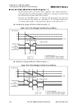
In PWM mode, the 16-bit PPG cycle setting buffer register (PCSRHn, PCSRLn) values are
loaded and the 16-bit downcounter starts down-count operation when a software trigger is
input or a hardware trigger by TRGn pin input is input. When the count value reaches "1", the
16-bit PPG cycle setting buffer register (PCSRHn, PCSRLn) values are reloaded to repeat the
down-count operation.
The initial state of the PPG output is "L". When the 16-bit downcounter value matches the
value set in the duty setting registers, the output changes to "H" synchronizing with count
clock. The output changes back to "L" when the "H" was output until the value of duty setting.
(The output levels will be reversed if OSEL is set to "1".)
When the retrigger function is disabled (RTRG = 0), software triggers (STRG = 1) are ignored
during the operation of the downcounter.
When the downcounter is not running, the maximum time between a valid trigger input
occurring and the downcounter starting is as follows.
Software trigger
: 1 count clock cycle + 2 machine clock cycles
Hardware trigger by TRGn pin input : 1 count clock cycle + 3 machine clock cycles
The minimum time is as follows.
Software trigger
: 2 machine clock cycles
Hardware trigger by TRGn pin input : 3 machine clock cycles
When the downcounter is running, the maximum time between a valid retrigger input occurring
and the downcounter restarting is as follows.
Software trigger
: 1 count clock cycle + 2 machine clock cycles
Hardware trigger by TRGn pin input : 1 count clock cycle + 3 machine clock cycles
The minimum time is as follows.
Software trigger
: 2 machine clock cycles
Hardware trigger by TRGn pin input : 3 machine clock cycles
Содержание MB95630H Series
Страница 2: ......
Страница 4: ......
Страница 8: ...iv ...
Страница 20: ...xvi ...
Страница 106: ...MB95630H Series 86 FUJITSU SEMICONDUCTOR LIMITED MN702 00009 1v0 E CHAPTER 6 I O PORT 6 2 Configuration and Operations ...
Страница 282: ...MB95630H Series 262 FUJITSU SEMICONDUCTOR LIMITED MN702 00009 1v0 E CHAPTER 14 LIN UART 14 8 Notes on Using LIN UART ...
Страница 642: ...MB95630H Series 622 FUJITSU SEMICONDUCTOR LIMITED MN702 00009 1v0 E APPENDIX A Instruction Overview A 5 Instruction Map ...
Страница 644: ......


