MB95630H Series
278
FUJITSU SEMICONDUCTOR LIMITED
MN702-00009-1v0-E
CHAPTER 15 8/10-BIT A/D CONVERTER
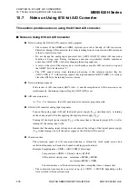
15.7 Notes on Using 8/10-bit A/D Converter
15.7
Notes on Using 8/10-bit A/D Converter
This section provides notes on using the 8/10-bit A/D converter.
■
Notes on Using 8/10-bit A/D Converter
●
Note on setting the 8/10-bit A/D converter with a program
•
The contents of the ADDH and ADDL registers are saved at the end of A/D conversion.
Therefore, during A/D conversion, the values resulting from last conversion will be returned
if the two registers are read.
•
Do not change the analog input pin select bits (ADC1:ANS[3:0]) while AD conversion
function is being used. During continuous activation in particular, disable continuous
activation (ADC2: EXT = 0) before changing the analog input pin.
•
A reset, or the start of the stop mode or watch mode causes the A/D converter to stop and
the ADMV bit to be cleared to "0".
•
The CPU cannot return from interrupt processing if the interrupt request flag bit
(ADC1:ADI) is "1" with interrupt requests having been enabled (ADC2:ADIE = 1). Always
clear the ADI bit in the interrupt service routine.
●
Note on interrupt requests
If the restart of A/D conversion (ADC1:AD = 1) and the completion of A/D conversion occur
simultaneously, the interrupt request flag bit (ADC1:ADI) is set.
●
A/D conversion error
As | Vcc - Vss | decreases, the A/D conversion error increases proportionately.
●
8/10-bit A/D converter analog input sequences
Turn on the analog input (AN) and the digital power supply (V
CC
) simultaneously, or turning
on the analog input (AN) after applying the digital power supply (V
CC
).
Turning off the digital power supply (V
CC
) at the same time as the analog input (AN), or after
turning off the analog input (AN).
Ensure that the analog input voltage does not exceed the voltage of the digital power supply
(V
CC
) when turning on or off the power supply of the 8/10-bit A/D converter.
●
Conversion time
The conversion speed of A/D conversion function is affected by clock mode, main clock
oscillation frequency and main clock speed switching (gear function).
Example: Sampling time = CKIN
×
(ADC2:TIM[1:0] settings)
Compare time = CKIN
×
10 (fixed value) + MCLK
A/D converter startup time:
minimum = MCLK + MCLK
maximum =MCLK + CKIN
Conversion time = A/D converter startup time + sampling time + compare time
•
The conversion time may have an error of up to (1 CKIN – 1 MCLK), depending on the
time at which A/D conversion starts.
Содержание MB95630H Series
Страница 2: ......
Страница 4: ......
Страница 8: ...iv ...
Страница 20: ...xvi ...
Страница 106: ...MB95630H Series 86 FUJITSU SEMICONDUCTOR LIMITED MN702 00009 1v0 E CHAPTER 6 I O PORT 6 2 Configuration and Operations ...
Страница 282: ...MB95630H Series 262 FUJITSU SEMICONDUCTOR LIMITED MN702 00009 1v0 E CHAPTER 14 LIN UART 14 8 Notes on Using LIN UART ...
Страница 642: ...MB95630H Series 622 FUJITSU SEMICONDUCTOR LIMITED MN702 00009 1v0 E APPENDIX A Instruction Overview A 5 Instruction Map ...
Страница 644: ......


