


MB39A104
5
■
ABSOLUTE MAXIMUM RATINGS
* : The packages are mounted on the epoxy board (10 cm
×
10 cm).
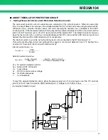
WARNING: Semiconductor devices can be permanently damaged by application of stress (voltage, current,
temperature, etc.) in excess of absolute maximum ratings. Do not exceed these ratings.
■
RECOMMENDED OPERATING CONDITIONS
* : Refer to“
■
SETTING THE TRIANGULAR OSCILLATION FREQUENCY”.
WARNING: The recommended operating conditions are required in order to ensure the normal operation of the
semiconductor device. All of the device’s electrical characteristics are warranted when the device is
operated within these ranges.
Always use semiconductor devices within their recommended operating condition ranges. Operation
outside these ranges may adversely affect reliability and could result in device failure.
No warranty is made with respect to uses, operating conditions, or combinations not represented on
the data sheet. Users considering application outside the listed conditions are advised to contact their
representatives beforehand.
Parameter
Symbol
Condition
Rating
Unit
Min
Max
Power supply voltage
V
CC
VCC, VCCO terminal
⎯
20
V
Output current
I
O
OUT1, OUT2 terminal
⎯
60
mA
Output peak current
I
OP
Duty
≤
5
%
(t
=
1/f
OSC
×
Duty)
⎯
700
mA
Power dissipation
P
D
Ta
≤
+
25
°
C
⎯
740*
mW
Storage temperature
T
STG
⎯
−
55
+
125
°
C
Parameter
Symbol
Condition
Value
Unit
Min
Typ
Max
Power supply voltage
V
CC
VCC, VCCO terminal
7
12
19
V
Reference voltage output current
I
REF
VREF terminal
−
1
⎯
0
mA
VH output current
I
VH
VH terminal
0
⎯
30
mA
Input voltage
V
INE
−
INE1,
−
INE2 terminal
0
⎯
V
CC
−
0.9
V
V
DTC
DTC1, DTC2 terminal
0
⎯
V
CC
−
0.9
V
Control input voltage
V
CTL
CTL terminal
0
⎯
19
V
Output current
I
O
OUT1, OUT2 terminal
−
45
⎯
+
45
mA
Output Peak current
I
OP
Duty
≤
5
%
(t
=
1/f
OSC
×
Duty)
−
450
⎯
+
450
mA
Oscillation frequency
f
OSC
Overcurrent detection
by ON resistance of FET
100
500
1000
kHz
*
100
500
1500
kHz
Timing capacitor
C
T
⎯
39
100
560
pF
Timing resistor
R
T
⎯
11
24
130
k
Ω
VH terminal capacitor
C
VH
VH terminal
⎯
0.1
1.0
µ
F
Soft-start capacitor
C
S
CS1, CS2 terminal
⎯
0.1
1.0
µ
F
Short-circuit detection capacitor
C
SCP
CSCP terminal
⎯
0.1
1.0
µ
F
Reference voltage output
capacitor
C
REF
VREF terminal
⎯
0.1
1.0
µ
F
Operating ambient temperature
Ta
⎯
−
30
+
25
+
85
°
C
Содержание MB39A104
Страница 38: ...MB39A104 38 MEMO ...
Страница 39: ...MB39A104 39 MEMO ...


