Fujitsu MB2145-507 Скачать руководство пользователя страница 47

34

APPENDIX

Содержание MB2145-507

Страница 1: ...FUJITSU SEMICONDUCTOR CONTROLLER MANUAL F MC 16L 16LX 16F EMULATION POD MB2145 507 HARDWARE MANUAL CM42 00411 1E ...

Страница 2: ...se the MB2145 507 emulation pod hereafter emulation pod to develop application products that use the F2MC 16L 16LX 16F series devices Product Environment The emulation pod operates properly at a temperature of 5 C to 45 C and a humidity of 30 to 80 Do not use in high temperature and high humidity environments or in any environment where condensation will form Do not put heavy objects on the emulat...

Страница 3: ...le Next contact the distributor Using the emulation pod in an abnormal state may cause a failure fire or electric shock 8 If you hear thunder disconnect the power plug from the receptacle Using the emulation pod during a thunderstorm can damage the emulation pod or cause a fire 9 Electric shock Before connecting or disconnecting cables turn off the power to the emulation pod and connected devices ...

Страница 4: ...ay cause a failure fire or electric shock 10 Do not insert or drop any metallic combustible or other object through a ventilation or other type of opening in the emulation pod Doing so may cause a failure fire or electric shock 10 Do not use a voltage other than the indicated power voltage Do not connect the power cord in a daisy chain Doing so may cause a fire or electric shock 10 Do not damage o...

Страница 5: ... electric field Doing so may cause a failure 11 When disconnecting the power plug or a cable hold the power plug or connector itself Do not pull on the cable Pulling on a cable may cause the core wire to be exposed or cut resulting in a failure fire or electric shock 11 12 To prevent damage from static electricity do not let a finger or object contact a connector pin 12 Do not block the emulation ...

Страница 6: ...cause an electric shock 27 When turning on the power follow the procedure described in the manual Failure to do so may cause a device failure 28 After the emulation pod power is turned on do not turn off and turn on the user system power Doing so cause a device failure 28 When power is on do not carry the emulation pod or subject it to shock or vibration Doing so may cause a device failure 28 When...

Страница 7: ... arising from the use of this information or circuit diagrams 3 The contents of this document may not be reproduced or copied without the permission of FUJITSU LIMITED 4 FUJITSU semiconductor devices are intended for use in standard applications computers office automation and other office equipment industrial communications and measurement equipment personal or household devices etc CAUTION Custo...

Страница 8: ...s a summary of the section below the section title You will get an overview of the product by reading only the summaries Since the upper level section title also appears in a lower level section you always know which upper level section your current reading belongs to ...

Страница 9: ...viii ...

Страница 10: ...CHAPTER 2 CONNECTION AND SETTINGS 15 2 1 System Configuration 16 2 2 Connecting the 2140 Main Unit 17 2 3 Connecting the Probe Cable 19 2 4 Connecting the External Probe 20 2 5 Mounting the Evaluation MCU 22 2 6 Supplying a Clock to the Evaluation MCU 23 2 7 Switching the Power Source 25 2 8 Switching the C Pin Circuit Connection 27 2 9 Power on Sequence 28 2 10 Power off Sequence 29 APPENDIX 31 A...

Страница 11: ...ure 2 2 1 Connecting the 2140 Main Unit 18 Figure 2 3 1 Connecting the Probe Cable 19 Figure 2 4 1 Connecting the External Probe 20 Figure 2 5 1 Mounting the Evaluation MCU 22 Figure 2 6 1 Clock Peripheral Circuit 23 Figure 2 6 2 Crystal Mounting Example 24 Figure 2 7 1 Jumper Switch for the Power Supply Route 25 Figure 2 8 1 Jumper Switch and C pin Circuit Connection 27 Figure 2 9 1 Power on Sequ...

Страница 12: ... 13 Table 2 4 1 External Probe Data 21 Table 2 6 1 Clock Switching Method 24 Table 2 7 1 How to Switch the Emulator specific Power Supply Circuit Pin 25 Table 2 7 2 How to Set the Jumper Switch for the Power Supply Ports 26 Table 2 8 1 Jumper Switch for Setting the C pin Circuit Connection 27 Table A 1 Pins to which a Buffer Circuit is Added 33 ...

Страница 13: ...xii ...

Страница 14: ...pecifications Before using the emulation pod read this chapter and check that the product and accessories are complete 1 1 Checking the Components 1 2 Drawings of Emulation Pod and Names of Parts 1 3 General Specifications 1 4 Optional Products 1 5 Note on Errors 1 6 Notes on Handling the Emulation Pod 1 7 Notes on Use ...

Страница 15: ...hat no component is missing Checking the Components Before using the emulation pod check that the following component has been provided Emulation pod main unit 1 Caution The device can be damaged during transport Store the packing materials used to ship the emulation pod and use them if you need to transport it CAUTION ...

Страница 16: ...ion gives the names of the emulation pod parts For information on connection and settings see Chapter 2 Connection and Settings Views of Emulation Pod and Names of Parts Figures 1 2 1 to 1 2 4 shows views of the emulation and names of parts of its various parts Figure 1 2 1 Appearance of Emulation Pod Top View ...

Страница 17: ... source jumper Jumper for changing the power source 5 MCU mounting socket IC socket for mounting the evaluation MCU 6 UVCC LED LED indicating the status of the evaluation MCU power Lights when the user system power is from 1 8 V to 5 5 V EXEC LED Lights during program execution HOLD LED Lights in the hold state SLEEP LED Lights in the sleep state STOP LED Lights in the stop state RESET LED Lights ...

Страница 18: ...Drawings of Emulation Pod and Names of Parts Figure 1 2 4 Appearance of Emulation Pod Rear View No Name Description 1 Main unit interface cable connector Connector for connecting the main unit interface cable ...

Страница 19: ... ambient temperature or humidity outside the specified range may cause a device failure Always use the emulation pod within the specified temperature and humidity range Table 1 3 1 General Specifications Item Specification Name F2MC 16L 16LX 16F emulation pod Model MB2145 507 Power Emulator power Voltage 5V 5 User system power Voltage 1 8 V to 5 5 V 1 Current consumption 40 mA maximum 2 Operating ...

Страница 20: ...Optional Products 1 The model differs according to the package For details contact the Fujitsu sales division 2 The model differs according to the evaluation MCU used For details contact the Fujitsu sales division Table 1 4 1 Optional Products Name Model 2140 main unit MB2141A Probe cable 1 External probe MB2142 11 Evaluation MCU MB90Vxxx 2 ...

Страница 21: ...tacle When the smoke has disappeared ask the distributor to repair the emulation pod Never make repairs yourself since it is very dangerous Using the emulation pod in an abnormal state may cause a fire or electric shock If water or other liquid a metallic object or other foreign substance gets inside the emulation pod immediately turn off the power and disconnect the power plug from the receptacle...

Страница 22: ...tor inlet Putting your fingers in the connector inlet can result in an electric shock or failure Plug If you hear thunder disconnect the power plug from the receptacle Using the emulation pod during a thunderstorm can damage the emulation pod or cause a fire No disassembly Never open the emulation pod case Do not modify the emulation pod without permission Opening the case or modifying the emulati...

Страница 23: ...o not use a voltage other than the indicated power voltage Do not connect the power cord in a daisy chain Doing so may cause a fire or electric shock Do not damage or alter any cables Putting a heavy object on a cable or pulling forcibly bending distorting or heating a cable may damage the cable and cause a fire or electric shock Plug Before moving the emulation pod disconnect the power plug from ...

Страница 24: ...or cause the emulation pod to fall When disconnecting the power plug or a cable hold the power plug or connector itself Do not pull on the cable Pulling on a cable may cause the core wire to be exposed or cut resulting in a failure fire or electric shock Do not put the emulation pod in a location near a speaker or television tuner or in any location subject to a magnetic or electric field Doing so...

Страница 25: ...m static electricity do not let a finger or object contact a connector pin Do not block the emulation pod s ventilation openings Blocking ventilation openings causes heat to accumulate and may cause a fire CAUTION Prohibition Do not subject the emulation pod to a shock Doing so may cause a failure Do not place the emulation pod in direct sunlight in a high temperature or high humidity environment ...

Страница 26: ...mbient operating and storage temperature and humidity Table 1 7 1 Ambient Operating and Storage Temperature and Humidity Temperature Humidity During operation 5 C to 35 C 30 to 80 no condensation In storage 20 C to 70 C 20 to 90 no condensation ...

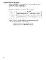
Страница 27: ...14 CHAPTER 1 PRODUCT HANDLING AND SPECIFICATIONS ...

Страница 28: ...ad this chapter before turning the power on 2 1 System Configuration 2 2 Connecting the 2140 Main Unit 2 3 Connecting the Probe Cable 2 4 Connecting the External Probe 2 5 Mounting the Evaluation MCU 2 6 Supplying a Clock to the Evaluation MCU 2 7 Switching the Power Source 2 8 Switching the C Pin Circuit Connection 2 9 Power on Sequence 2 10 Power off Sequence ...

Страница 29: ...d is designed to be connected a host machine from which the emulation pod will be controlled System Configuration Figure 2 1 1 shows the emulation pod system configuration 1 RS232C cable 2 Main unit interface cable 3 Probe cable 4 External probe Figure 2 1 1 System Configuration ...

Страница 30: ...onnectors on the back of the emulation pod as shown in Figure 2 2 1 Connecting the 2140 Main Unit Prohibition Before connecting or disconnecting a cable turn off the power Failure to do so may cause an electric shock When disconnecting a cable hold the cable by the connector case Do not pull on the cable Doing so may break s wire in the cable CAUTION ...

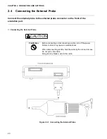
Страница 31: ...18 CHAPTER 2 CONNECTION AND SETTINGS Figure 2 2 1 Connecting the 2140 Main Unit ...

Страница 32: ...od as shown in Figure 2 3 1 Connecting the Probe Cable Figure 2 3 1 Connecting the Probe Cable Prohibition Before connecting or disconnecting a cable turn off the power Failure to do so may cause an electric shock When disconnecting a cable hold the cable by the connector case Do not pull on the cable Doing so may break a wire in the cable CAUTION ...

Страница 33: ... the emulation pod Connecting the External Probe Figure 2 4 1 Connecting the External Probe Prohibition Before connecting or disconnecting a cable turn off the power Failure to do so may cause an electric shock When disconnecting a cable hold the cable by the connector case Do not pull on the cable Doing so may break a wire in the cable CAUTION ...

Страница 34: ... Do not add stress by pulling on the external probe Firmly connect the connector that connects the external probe to the emulation pod Table 2 4 1 External Probe Data Color External probe data Color External probe data Black CH0 channel 0 input Green CH5 channel 5 input Brown CH1 channel 1 input Blue CH6 channel 6 input Red CH2 channel 2 input Purple CH7 channel 7 input Orange CH3 channel 3 input ...

Страница 35: ...ation MCU in the evaluation MCU IC socket on the top of the emulation pod as shown in Figure 2 5 1 Mounting the Evaluation MCU Figure 2 5 1 Mounting the Evaluation MCU Prohibition Before mounting the evaluation MCU turn off the power Failure to do so may cause an electric shock CAUTION ...

Страница 36: ...uation MCU using the clock switch and secondary clock supply jumper on the top of the emulation pod as shown in Figure 2 6 2 and Table 2 6 1 Supplying a Clock to the Evaluation MCU Figure 2 6 1 Clock Peripheral Circuit Prohibition Before operating the clock switch turn off the power Failure to do so may cause an electric shock CAUTION ...

Страница 37: ...on circuit in the user system Include a buffer such as the CMOS buffer in the circuit then supply the clock via the buffer Table 2 6 1 Clock Switching Method Clock supply method SW1 setting S1 setting Main clock Secondary clock 1 2 3 4 Crystal area Yes OFF OFF OFF OFF B1 C1 B2 C2 shorted No OFF OFF ON ON A1 B1 A2 B2 shorted User system Yes ON ON OFF OFF B1 C1 B2 C2 shorted No ON ON ON ON A1 B1 A2 ...

Страница 38: ...c power supply contact the Fujitsu sales division 1 Jumper switch for the user power supply port 0 2 Jumper switch for the user power supply port 1 3 Jumper switch for the emulator specific power supply circuit pin Figure 2 7 1 Jumper Switch for the Power Supply Route Prohibition Before setting the jumper switch for the power supply turn off the power Failure to do so may cause an electric shock C...

Страница 39: ...sed for the power supply Example When port 0 is UVCC1 and port 1 is UVCC2 Jumper setting for port 0 A B side shorted UVCC1 side Jumper setting for port 1 B C side shorted UVCC2 side Table 2 7 2 How to Set the Jumper Switch for the Power Supply Ports Number of power supply routes S2 setting Jumper setting for port 0 1 Jumper setting for port 1 1 1 route A B shorted UVCC1 side A B shorted UVCC1 side...

Страница 40: ...in switch depending on whether there is a C pin on the evaluation MCU Make the setting according to Table 2 8 1 Figure 2 8 1 Jumper Switch and C pin Circuit Connection Prohibition Before setting the jumper switch for the C pin circuit connection turn off the power Failure to do so may cause an electric shock CAUTION Table 2 8 1 Jumper Switch for Setting the C pin Circuit Connection C pin function ...

Страница 41: ... 2 9 1 Power on Sequence To turn on the power of the emulation pod press the power switch on the rear of the 2140 main unit toward the I side Prohibition When turning on the power follow the procedure described in the manual Failure to do so may cause a device failure After the emulation pod power is turned on do not turn off and turn on the user system power Doing so may cause a device failure Wh...

Страница 42: ...ence Turn off the power using the sequence shown in Figure 2 10 1 Figure 2 10 1 Power off Sequence To turn off the power of the emulation pod press the power switch on the rear of the 2140 main unit toward the 0 side Prohibition When turning off the power follow the procedure described in the manual Failure to do so may cause a device failure CAUTION ...

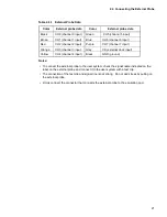
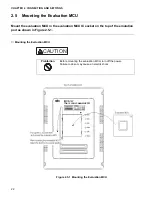
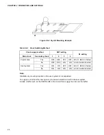
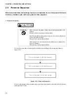
Страница 43: ...30 CHAPTER 2 CONNECTION AND SETTINGS ...

Страница 44: ...31 APPENDIX This appendix explains the differences between the emulation pod and a production MCU Appendix A Differences between the Emulation Pod and a Regular Production MCU ...

Страница 45: ...ion MCU When the emulation pod is used a buffer circuit is added to some pins for control of the evaluation MCU This produces electrical characteristic different from a regular production MCU Differences between the Emulation Pod and a Regular Production MCU Figure A 1 Buffer Circuit ...

Страница 46: ...s to which a buffer circuit is added The pin names listed in the table are the pin names of the evaluation MCU For the relationship to the actual MCU contact the Fujitsu sales division Table A 1 Pins to which a Buffer Circuit is Added Evaluation MCU pin name Evaluation MCU pin name P00 P10 P01 P11 P02 P12 P03 P13 P04 P14 P05 P15 P06 P16 P07 P17 ...

Страница 47: ...34 APPENDIX ...

Страница 48: ... 1E FUJITSU SEMICONDUCTOR CONTROLLER MANUAL F MC 16L 16LX 16F EMULATION POD MB2145 507 HARDWARE MANUAL July 1998 the first edition Published FUJITSU LIMITED Electronic Devices Edited Technical Communication Dept ...

Страница 49: ......

Отзывы: