background image

Содержание M255XK

Страница 1: ...M255XK 51 4 Mini Flexible Disk Drive Customer Engineering Manual FUJITSU TS021 013087 01 70221 Rev A ...

Страница 2: ......

Страница 3: ...comments on this publication to FUJITSU AMERICA INC 3055 Orchard Drive San Jose CA 95134 USA TEL 408 432 1300 FAX 408 432 1318 TLX 230 176207 TWX 910 338 2193 The contents of this manual are subject to change without prior notice Copyright 1987 FUJITSU AMERICA INC All Rights Reserved ii TS 021 013087 01 70221 Rev A ...

Страница 4: ...11 01 5 11 01 1 3 01 4 12 01 5 12 01 2 1 01 4 13 01 5 13 01 2 2 01 4 14 01 5 14 01 2 3 01 4 15 01 5 15 01 2 4 01 4 16 01 5 16 01 2 5 01 4 17 01 5 17 01 2 6 01 4 18 01 5 18 01 4 19 01 5 19 01 3 1 01 4 20 01 5 20 01 3 2 01 4 21 01 5 21 01 3 3 01 4 22 01 3 4 01 4 23 01 3 5 01 4 24 01 3 6 01 4 25 01 3 7 01 4 26 01 3 8 01 4 27 01 3 9 01 4 28 01 3 10 01 4 29 01 3 11 01 4 30 01 3 12 01 4 31 01 3 13 01 4 ...

Страница 5: ...ECTION 3 Tl EORV OF OPERATIONS 3 1 3 2 3 3 Construction and Functions 3 1 1 Frame Assembly 3 1 2 Door Opening Closing and Disk Clamp Mechanism 3 1 3 Spindle Mechanism 3 1 4 Read Write Head and Carriage 3 1 5 Seek Mechanism 3 1 6 Write Protect Detection 3 1 7 Track 00 Detection 3 1 8 Index Detection 3 1 9 Diskette Inserted Detection 3 1 10 Head Load Mechanism 3 1 11 Door Lock Mechanism Circuit Oper...

Страница 6: ...ustment 4 4 13 Head Load Inspection and Adjustment 4 4 14 Door Lock Inspection 4 5 Removal and Replacement Procedures 4 5 1 Head Carriage Replacement 4 5 2 Stepping Motor and Steel Band Replacement 4 5 3 Spindle Motor Replacement 4 5 4 Collet Assembly Replacement 4 5 5 Sensor Block Replacement 4 5 6 Main Circuit Card Replacement 4 5 7 Write Protect Sensor Replacement 4 5 8 Bezel Replacement 4 5 9 ...

Страница 7: ...tions M2552K Revision 1 Circuit Card Jumper Locations Disk Drive Orientation During Maintenance Collet Shaft Adjustment Bail Height Adjustment Bail Adjustment Write Protect Sensor Head Contact Inspection Asymmetry Measurement Average Read Level Measurement 2F Resolution Measurement Lobe Pattern for Track Alignment Track Alignment Adjustment Track 00 Sensor Adjustment Index Burst Timing Index Senso...

Страница 8: ...ess Mechanism INDEX Pulse Read Write Head and Track Specifications Power Supply Requirements Environmental Conditions Reliability Regulatory Agency Certification Interface Signal Pin Designation 4 1 Inspection and Adjustment Items 4 2 Field Replaceable Items 4 3 Maintenance Tools 4 4 Screw Size and Torque 4 5A M2553K 54K Revision 2 Circuit Card Jumper Definitions 4 5B M2553K Revision 3 Circuit Car...

Страница 9: ...ulation or MFM Modified Frequency Modulation recording methods are acceptable There are three Models in the M255XK Family M2552K This model records 5 922 flux transitions per il1ch and has a per disk unformatted storage capacity of 1 Mbyte with MFM Encoding or 500 Kbytes with FM Encoding With a 16 sector format 256 bytes per sector the M2552K emulates a double density double sided 96 track per inc...

Страница 10: ...gnal line for 300 or 360 RPM On all Models Track density is 96 TPI and there ere 80 cylinders 160 tracks per disk Track to track access time is 3 milliseconds plus a 15 millisecond settling time Average access time including settling time is 94 milliseconds Except for the differences listedabove performance of the units is identical Refer to the M255XK Product Description Manual for an overview of...

Страница 11: ...d Unload the Read Write heads in the disk drive via an interface signal line o Auto Rezero Rotates the diskette to full speed and retracts the Read Write heads to Track 00 whenever power is turned on o Door Lock Allows the door lever to be locked to prevent media removal when the drive is selected or when In Use is selected o Door Switch Allows the Ready signal to be active whenever the door is cl...

Страница 12: ......

Страница 13: ...mm Depth With Bezel B 19 0 02 inches 20B 0 5mm Without Bezel B OO 0 02 inches 203 0 5mm Without power or interface cable connector Weight 3 10 pounds 1 2 Kg maximum Signal Power 1 6 41mm 10 Connector Connector 5 5 139 7mm JOmm 0 0 S 7S l46mm I 1 8 10 06 1 6 1 45 5mm 40mm I r L_ _ V L l J PCB I N I _ NN c ClCl NV 3 3 3 3 I I ___________ J 11 5 82 48 0mm 1 S 1 9 r J8mm 47mm I Figure 2 1 External Out...

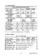
Страница 14: ...NCH 5922 9646 5922 9646 TRACKS PER INCH 96TPI 96TPI 96TPI 96TPI I OF TRACKS 160 160 160 160 I OF CYLINDERS 80 80 80 80 TRANSFER RATE 250KBS 500KBS 250KBS 500KBS One half the given Storage Capacity values with FM Encoding 2 3 DISK MECHANISM Table 2 2 Disk Mechanism 300 RPM 360 RPM MODEL NUMBER M2552K M2553K M2554K M2554K SPINDLE SPEED 300 RPM 360 RPM 300 RPM 360 RPM AVERAGE LATENCY TIME 100 msec 83...

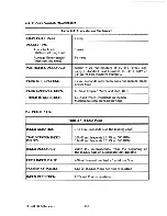
Страница 15: ...CARRIAGE DRIVE 4 Phase Stepper Motor and Steel Belt TRACK 00 DETECTION LED and Photo transistor Detection Mechanical stop on head carriage 2 5 INDEX PULSE Table 2 4 INDEX Pulse INDEX DURATION 1 to 8 milliseconds use the leading edge TIME BETWEEN INDEX 200 00 milliseconds t 1 5 at 300 RPM PULSES 166 67 milliseconds t 1 5 at 360 RPM INDEX ACCURACY 200 t 150 microseconds from the beginning of the IND...

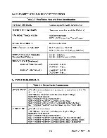
Страница 16: ...Lap 36 248mm Side 0 34 131mm Side 1 2 7 POWER REQUIREMENTS Table 2 6 Power Supply Requirements 12 VOLTS DC 5 allowable variance during read write operations and 10 at other times 200 millivolt maximum peak to peak ripple voltage including noise spikes 0 22 Amperes average current draw 0 60 Amperes maximum average current draw 0 90 Amperes peak current draw Spindle Motor start up 0 07 Amperes maxim...

Страница 17: ...s with conditions conforming to JIS Z0200 Provisions for Correctly Packed Freight Testing Methods Level II When transport takes place over an extended period such as trans oceanic by ship the Storage Environmental Conditions apply 2 9 RELIABILITY Table 2 8 Reliability MEAN TIME BETWEEN FAILURES MTBF 11 000 Power on hours with 25 duty cycle MEAN TIME TO REPAIR 30 Minutes Maximum to subassembly leve...

Страница 18: ...in the M255XA Product Description Manual Table 2 10 lists the Interface Pin Designations Table 2 10 Interface Signal Pin Designation Signal Pin Return Pin Signal Name Direction Number Number HD Hi Density LSP Speed Out In 2 1 IN USE HEAD LOAD Input 4 3 DRIVE SELECT 3 Input 6 5 INDEX PULSE Output B 7 DRIVE SELECT 0 Input 10 9 DRIVE SELECT 1 Input 12 11 DRIVE SELECT 2 Input 14 13 MOTOR ON Input 16 1...

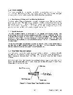
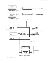
Страница 19: ...ding medium has the ability to interchange data with other 5i disk drives As with all high precision equipment excessive shock and vibration must be avoided and only trained maintenance personnel should service the unit Refer to the Overall Block Diagram in Figure 3 1 T5 021 013087 01 fapetic bead Track 00 sensor wi r J Door lock soleuoid File protect sensor r File protect sensor LED Disk IDdex se...

Страница 20: ... a service life of 20 000 or more hours of continuous operation The spindle motor rotates at 300 or 360 RPM and maintains a constant speed even with load and temperature fluctuations by using feedback signals from an AC tachometer built into the motor The spindle and collet are precisely aligned to prevent injury to the center hole of the disk and to allow accurate centering of the disk This also ...

Страница 21: ...f a write command is given The LED is mounted on the spindle motor circuit card and the photo transistor sensor is mounted on the write protect circuit card assembly 3 1 7 Track 00 Detection The Track 00 detector is comprised of an LED and photo transistor assembly photo interrupter and a mechanical stop The photo interrupter provides a signal to the drive s circuitry whenever the head carriage is...

Страница 22: ...the front lever during all read or write operations to prevent the door from being opened and causing damage or the lost of data The door lock mechanism is comprised of the door lock solenoid eject assembly and associated parts 3 2 CIRCUIT CPERATIONS The drive s electronic circuitry is comprised of three major sections Read Write Circuits explained in paragraph 3 2 1 Control Circuits explained in ...

Страница 23: ...pre amp a subtraction amplifier and spurious noise components are removed by a low pass filter The amplified signal then goes to the differential amp The differential amp shifts the playback signal to the zero crossover position and simultaneously applies the proper amount of compensation in accordance with the difference in the frequency components The signal is further amplified The output from ...

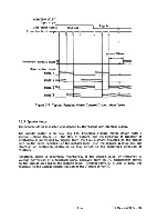
Страница 24: ... positioned approximately 0 58mm behind the Read Write gap and the erase gate signal is activated to allow for this offset from the turn on time of the Write Gate signal Refer to the write circuit timing diagram in Figure 3 5 Writing is enabled by 12 Volts being applied to the center tap of the Read Write head when the Write Gate interface signal is set true and Write Protect is false Externally s...

Страница 25: ... I t3 1 Previous petization Figure 3 5 Typical Write Circuit Waveforms Low Voltage Detection circuits are provided to sense low and unstable DC voltages The output of the low voltage detection circuits prevent the disk drive from writing or erasing if the supplied voltage 5 or 12 VDC is low or unstable These low voltage detection circuits are activated as follows 5 VDC circuit will activate if 5 V...

Страница 26: ...te and Erase coils in the selected Read Write Head for recording on the disk These circuits operate in conjunction with the Write Gate interface signal Erase current is delayed the required period of time to correspond to the beginning and ending of write current Spindle Motor Gate This output circuit determines the speed of the spindle motor Ready Detect Circuits This circuit receives Index pulse...

Страница 27: ...d date TS 021 013087 01 4 Door l ocJt drive cinait t Door lock IOleooid 1IMd load soleDOid Fl ODt bezel iadicator IDPUt si Dal Buffer FDMC IDterface OIltplt Floppy Disk Drive si Da1 tfechaoisll Q otrol LSl r e Buffer Spindle IIOtor I 1Over drive circuit 1 Stepping mtor driver Figure 3 6 Control Circuits 3 9 Stepping IDOtor ...

Страница 28: ... IC The flow of current and the switching of direction of excitation is performed by signals from the Hall element mounted on the circuit card on the outer periphery of the motor s rotor with the sequential drive coil and direction of excitation controlled so they switch to the prescribed direction of rotation Rotational speed is accurately maintained at the desired value by frequency to voltage c...

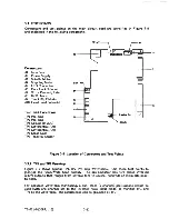
Страница 29: ...se Gate TP7 Track 00 Sensor J8 Lot NO t Jl0 Jl r I Draviag No ISSUE I I I I I I 32 L __ _ o Figure 3 8 Location of Connectors and Test Points 3 3 1 TPI and TP2 Pre Amp Figure 3 9 shows typical TP1 TP2 Pre amp Waveforms Use these test points to monitor the Read Write head output The pre ampllfier has two phase inverted 1800 outputs that ranges from several tens to several hundreds of mUllvolts peak...

Страница 30: ...veforms f A Figure 3 10 TP4 TP5 Typical Differential Amp Waveform For accurate waveform monitoring a dual trace 2 channeI oscilloscope should be used with one channel set to the inverted ADD input mode to monitor TP4 and TP5 as one waveform The oscilloscope can be grounded at TP3 TP4 and TP5 are available for checking the overall operation of the read write head and amplifiers and for checking tra...

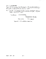
Страница 31: ...terface signal this signal is Low only when the head is at or near track 00 Note Track 00 output signal becomes True low level while the basic excitation phase for the stepping Motor is excited Because of this the timing of the waveform variation is not constant Track 00 sensor track 02 J m level track 00 Figure 3 12 TP7 Track 00 Detect Waveforms TS 021 0130B7 01 3 13 ...

Страница 32: ......

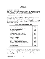
Страница 33: ...stment Items Item Refer To Collet Assembly Centering Adjustment 4 4 1 Bail Inspection and Adjustment 4 4 2 Disk in Sensor Inspection 4 4 3 Write Protect Senor Inspection 4 4 4 Disk Speed Inspection and Adjustment 4 4 5 Head Contact Inspection and Adjustment 4 4 6 Asymmetry Inspection and Adjustment 4 4 7 Read Level Inspection 4 4 8 Resolution Inspection 4 4 9 Track Inspection and Adjustment 4 4 10...

Страница 34: ...f defective 4 4 10 LED Circuit Card JA4 5716 If defective 4 4 11 Note 1 Obtain replacement part number from the old Circuit Card Note 2 Front Bezel and Front Lever Assembly part numbers are black items order other colors with a color drawing number 4 1 3 Tools Required for Maintenance Table 4 3 list the tools that may be required to perform an inspection replace mentor adjustment procedure Table 4...

Страница 35: ...ons are observed whenever working on the disk drive 4 2 1 Screw Torque Unless otherwise specified all screws are tightened according to their size to the torque values listed in Table 4 4 Table 4 4 Screw Size and Torque Screw Size Torque M2 11 Inch Pounds 2 Kilograms cm M2 6 24 Inch Pounds 4 5 Kilograms cm M3 33 Inch Pounds 6 Kilograms cm M3 setscrew 24 Inch Pounds 4 5 Kilograms cm 4 2 2 Screw Loc...

Страница 36: ...sting or replacing parts Procedures in paragraph 4 4 do not include data Read Write checks connect the drive to a test system and perform a window margin test to ensure data integrity Diskette Never use a defective work or test diskette during a maintenance action Set Jumper Selections Set Drive Select DSO through DS3 and all jumper selections to be compati ble with the test system as given below ...

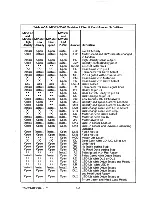
Страница 37: ...ty and Speed Control Latched Open Open Install SM2 Density and Speed Control Unlatched Install Install Install Open DSR Disk change reset with Drive Select Install STR Disk change reset with step Open MS Motor on with Drive Select Install Install Install Install MM Motor on with pin 16 Open Open Open Open JP3 Motor always on Install Install Install Install DK1 Disk in Sensor Enabled Open Open Open...

Страница 38: ...l Unlatched Open SM1 Density and Speed Control Latched Open RY Ready to pin 34 Shorted DC Disk Change to pin 34 Shorted RI Index gated with Pre Ready Open DI Index gated with Drive Select Open FG Frame Ground Open HL Head Load with pin 4 Open HS Head Load with Select Shorted HM Head Load with pin 16 Open 2 SP Motor speed and R W circuits changed in tandem Shorted 1 SP 360 RPM Only Open DSR Disk ch...

Страница 39: ...rive Select Install TM Terminator for input signal lines Open JPl No Index during Step Open JP2 No Read Data during Step Install RY Ready to pin 34 DO Door Switch Ready to pin 34 Open DC Disk Change to pin 34 Open In Use LED Lit with pin 4 HL Head Load with pin 4 Open HM Head Load with pin 16 Open HS Head Load with Select Open LC LED Lit with Drive Select and Ready Open LB LED Lit with LED 0 Insta...

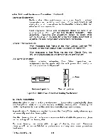
Страница 40: ... Ground point on the drive or on the user s system Disk Drive Orientation Unless indicated otherwise Disk Drive inspections and adjustments may be made with the unit placed horizontally or vertically as shown in Figure 4 2 Af RorizoDtal position Vertical positiOD Figure 2 Disk Drive Orientation During Maintenance 4 3 t EAD a EANING When the drive is used in a dusty environment it is advisable to p...

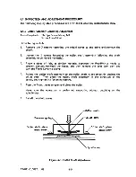
Страница 41: ... piece of felt or similar material between the Read Write heads to prevent contact between the heads and then release the door lock cam and turn the Front Lever to clamp 4 Adjust the collet shaft assembly so the collet shaft slides smoothly against the collet core Then press the collet shaft assembly in the direction of the arrow and tighten its fastening screws 5 Turn the Front Lever to open and ...

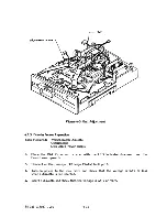
Страница 42: ...ficient clearance for the disk to be inserted without the jacket contacting either read write head 5 Repeat inserting and ejecting the disk 2 or 3 times to be certain the eject clamp operation is smooth 6 Check for sufficient clearance for the diskette to be inserted ejected without the head window the opening in the disk jacket through which the read write heads contact the disk surface catching ...

Страница 43: ...upply 1 Place the Disk Drive on its side with the LED indicator downward and the Front Lever upward 2 Connect an Oscilloscope DC range IV div to J9 pin 6 3 Turn on power to the disk drive and check that the voltage is 0 5V or less when a diskette is not inserted 4 Insert a diskette and check that the voltage is 2 5 V or more TS 021 0130B7 01 4 11 ...

Страница 44: ...shown in Figure 4 6 Be sure that notch A is above the light path of the Write Protect sensor 4 Move the Drive if strong external light is striking tile Write Protect sensor 5 Make sure the Write Protect interface signal pin 28 reads 0 5 volts or less with the jig at the notch A position with Disk Drive power turned on 6 Pull the jig out slightly so notch B is in the light path 7 Make sure the Writ...

Страница 45: ... Points on the main circuit card Set the oscilloscope range to AC rhode 0 2V 2 Load the work scratch diskette and start the Spindle Motor 3 Seek the Read Write heads to the innermost track 4 Record and then read a constant 2F on the entire track 2F is a l s only WRITE DATA frequency of 250kHz for M2552K and 500kHZ for M2553 54K 5 Write down the average values shown on the oscilloscope while perfor...

Страница 46: ...at spring that rides on the white part of the Read Write head may need adjustment refer to paragraph 4 4 2 Refer to paragraph 4 5 1 if the head carriage is defective and must be replaced c Deformation of the Diskette Deformation or bending of the diskette is checked by removing the diskette then slowly opening and closing the Front Lever while visually checking the Read Write heads to be sure the ...

Страница 47: ...ement Set the oscilloscope so 3 read data pulses can be observed and measured on the screen as shown in Figure 4 8 6 At the innermost track ensure the asymmetry is 600 nanoseconds or less for the M2552K or 300 nanoseconds or less for the M2553 54K 7 Repeat steps 4 through 6 for side 0 and side 1 8 If asymmetry standards are not met the following items are probable causes a A high concentration of ...

Страница 48: ... DATA frequency of 250kHz for M2552K and 500kHZ for M2553 54K 5 Measure the average Read Level value Vp p refer to Figure 4 9 ADD Yp p Figure 4 9 Average Read Level Measurement 2F 6 Ensure the Read Level true value is within the range shown below Innermost track Read Level 200mvp p or more all M225XK Models 7 Repeat steps 4 through 6 for side 0 and side 1 B If the results are not within the indica...

Страница 49: ...rd and then read the innermost track with a constant 2F WRITE OATA frequency with only l s recorded is 250kHZ for the M2552K and 500kHZ for the M2553 54K double the IF of step 4 7 Measure the average read level shown as V2F in Figure 4 10 ADD Figure 4 10 Resolution Measurement 8 Use the measured values of V1F and V2F in the following formula Resolution true value V2F X 100 V1F 9 Ensure the innermo...

Страница 50: ...econds per division Put one of the channels in invert mode and put both channels to ADD Connect the trigger input to pin B of the intra connector between the drive and exerciser 2 Start the Spindle Motor and load the alignment diskette 3 Seek the Read Write heads to Track 32 from track 0 outermost track 4 Check for a pattern of two lobes VA and VB levels need not coincide Figure 4 11 Lobe Pattern ...

Страница 51: ...he Read Write heads several tracks in and out until the Alignment Error is minimum d The adjustment should be made to minimize the Alignment Error for both side 0 and side 1 6 Tighten the 2 screws for the stepping motor in sequence a little at a time and repeat the adjustment if required until the Alignment Error is less than 20 see step 4 for how to measure this 20 when the screws are tightened t...

Страница 52: ...heads located away from Track 00 track 02 6 If the voltages measured in steps 3 and 5 are not within the specified range adjust the Track 00 sensor position as follows 7 Connect the oscilloscope s vertical input to TPI or TP2 pre amp Connect the Trigger to pin B of the Intraconnector Index Set the oscilloscope to AC mode 0 2 Volts per division and invert channel B Set Time Base to 20 milliseconds ...

Страница 53: ...ing screw Note Move the sensor cautiously Track 00 output voltage changes suddenly 13 Check steps 3 through 5 14 Repeat the adjustment until the values in steps 12 and 13 are within the specified range after tightening the mounting screw to the specified torque 15 Apply screw lock liquid to the head of the mounting screw Disk in sensor Disk in sensor TS 021 0130B7 01 track 00 sensor track 00 senso...

Страница 54: ...ning of each disk rotation 2 Start the Spindle Motor and load the alignment disk 3 Seek the Read Write heads to Track 02 4 Measure the duration of t in Figure 4 14 INDEX Pre amp 1 t Index bu rst delay Figure 4 14 Index Burst Timing 5 Ensure that Index Burst Timing is within the range of 200 150 microseconds for all models in the M255XK family Switch heads and reverify timing 6 Seek the read write ...

Страница 55: ... True Index Burst Timing is within the specified range given in step 6 b After tightening the mounting screw to the specified torque repeat the adjustment until the True Index Burst Timing is within thespecified range c Coat the head of the mounting screw with a small quantity of screw lock liquid 9 Remove the alignment disk Sensor position adjustment direction Indu seasor Index sensor mant screw ...

Страница 56: ...tart the Spindle Motor and load the alignment disk 4 Record a pattern of IF all zero s on Track 04 Write Data frequency of 125kHz for the M2552K and 500kHZ for the M2553 54K 5 Adjust Channel 2 output waveform using the oscilloscope s ranges and variable gain controls until the amplitude of Level A as shown in Figure 4 16 is equal to 5 divisions A Figure 4 16 Head Load SignallA 6 Refer to Figure 4 ...

Страница 57: ...the disk drive selected refer to Figure 4 19 tA Figure 4 19 Head Unload Signal nAn 10 Use the oscilloscope to measure Channel 2 output waveform B with the disk drive deselected refer to Figure 4 20 Figure 4 20 Head Unload Signal B 11 Check that B A X 100 is within the specified range repeat for Track 79 12 If the head load or unload level is out of specification see Figure 4 17 readjust the Head L...

Страница 58: ...he front level released to activate the door lock solenoid and lock the door Figure 4 21 Door Lock Solenoid Activated 3 Refer to Figure 4 22 Deselect the disk drive Ensure that the door lock solenoid is deactivated and the the door is released Figure 4 22 Door Lock Solenoid Deactivated 4 Select and deselect the drive several times to ensure that the door lock solenoid and stopper pin operate corre...

Страница 59: ... lower read write head 6 There are two fixing plates connecting the head carriage assembly and the steel band assembly Grasp fixing plate B Figure 5 5 item 12 and the head carriage Figure 5 5 item 7 with your fingers and push to disengage the steel band from band fixing plate B 7 Detach fixing plate B and the steel band spring Figure 5 5 item 13 from the head carriage and remove them at the same t...

Страница 60: ...e steel band in the pulley section of the stepping motor Note Carefully clean the surfaces of the steel band pulley and other mechanisms with alcohol and gauze before assembly 14 Reverse the procedures described in steps 6 and 7 to reconnect the steel band to the head carriage assembly use band fixing plate B and the band spring T5 021 013087 01 4 28 ...

Страница 61: ...rd and its shield plate lB Move the head carriage between the innermost track and Track 00 to ensure that the steel band stays straight and that there is no abnormal noise 19 Inspect head contact paragraph 4 4 6 20 Inspect asymmetry paragraph 4 4 7 21 Adjust track alignment paragraph 4 4 10 22 Adjust Track 00 sensor paragraph 4 4 11 23 Adjust Index Burst Timing paragraph 4 4 12 24 Check Read Level...

Страница 62: ...4 5 1 Head Carriage Replacement Continued PWB shield plate Figure 4 24B Head Cable Routing CoDDeCtor Figure 4 24C Head Cable Routing T5 021 013087 01 4 30 ...

Страница 63: ... Remove the mounting screws for the stepping motor pulley item 3 then remove the band washer and steel band B Remove the stepper motor mounting screws 9 Remove the screw fastening the STM bracket item 4 the STM bracket holds the stepping motor and then remove the stepping motor 10 Insert the new stepping motor and hold it in place with its mounting screws Note When replacing the stepping motor the...

Страница 64: ...nd lift up the circuit card item 43 unplug all connectors at the main circuit card assembly and remove the card 3 Remove the screws holding the main circuit card shield plate and remove the plate item 23 4 Remove the three spindle motor mounting screws from the spindle side and remove the spindle motor from the rotor circuit card side 5 Carefully insert the new spindle motor into the chassis insta...

Страница 65: ...unting screws to the specified torque 6 Inspect and adjust track alignment paragraph 4 4 10 7 Install the shield cover assembly 4 5 5 Sensor Block Replacement Tools Required Phillips Screwdriver M3 Tweezers Screw Lock Liquid Refer to Figure 5 5 1 Remove the shield cover item 44 2 Remove the mounting screws from the main circuit card and lift up the circuit card item 43 unplug all connectors at the...

Страница 66: ...it card assembly by reversing the removal procedure given above in steps 2 and 3 Note The Main Circuit Card is available at different revision levels obtain the correct Drawing Number from the replaced circuit card 5 Set the circuit card selection jumpers in the same positions as they were on the removed card refer to Figure 4 1 Table 4 5 6 Check asymmetry paragraph 4 4 7 7 Check read level paragr...

Страница 67: ...n the front lever item 42 to the open position and remove the front lever assembly paragraph 4 5 9 2 Remove the Bezel s mounting screws item S13 and the Bezel item 41 by pulling it forward 3 Install the new Bezel by reversing the procedures given in steps 1 and 2 Note When installing the new Bezel press both sides of the Bezel against the chassis and tighten the mounting screws to the specified to...

Страница 68: ... spring remove the E ring and remove the clamp cam assembly item 31 4 Install the new clamp cam assembly by reversing the removal procedure 5 Adjust the slack in the clamp shaft to 0 05 0 2mm by using washers item S20 Coat the part that contacts the clamp cam and set arm item 28 with lubricant 6 Install the Bezel and Front Lever by reversing the removal procedure Note When there is a head load mec...

Страница 69: ...main circuit card shield plate and remove the plate item 23 4 Remove the two screw holding the head load solenoid bracket and remove the solenoid assembly item 32 from the chassis 5 Install the new solenoid assembly by reversing the removal steps 6 Refer to Figure 4 26 Use the head load adjustment screw to adjust the height of the chassis and top of the vertical rod to 0 68 17 3mm and temporarily ...

Страница 70: ...e front lever and remove the front lever assembly paragraph 4 5 9 3 Remove the front bezel paragraph 4 5 8 4 Remove the mounting screws and the door lock solenoid item 39 Refer to Figure 4 27 5 Install a new door lock solenoid by reversing the removal procedure Clamp cam assembly Lock lever assembly tfount screw Figure 4 27 Door Lock Solenoid 4 38 TS 021 013087 01 ...

Страница 71: ...Intermediate Level Bottom Level Disk Drive Transport Components Chassis Upper Chassis Assembly Spindle Motor Stepping Motor Clamp Cam Assembly Collet Assembly Track 00 Block Assembly Bail Assembly Front Bezel Front Lever Assembly Steel Band Head Load Assembly Door Lock Assembly Head Carriage Assembly Read Write Heads Main Circuit Card Assembly Electronic Components Sensor Block Assembly Sensors TS...

Страница 72: ...ssembly Shield cowr assembly Hain PWB assembly IK UDt screw PWB shield plate ount screw Protect PWB assembly _o ar II Solenoid Clamp cam assembly I I 1 p iL Stepping IIOtor Front bezel llassis Front lever assembly Disk Drive motor Upper chassis Solenoid Figure 5 1 Top View of Disk Drive View 1 5 2 TS 021 013087 01 ...

Страница 73: ...mbly lIOunt screw Disk Drive otor lIOunt screw Lock lever assembly mount screw Solenoid assembly mount screw LED PWB assembly aunt screw Upper chassis lIIOunt screw Upper chassis Disk Drive motor Figure 5 2 Top View of Disk Drive View 2 T5 021 013087 01 5 3 ...

Страница 74: ...Stepping motor Hounting leg ou nt screw 80Wlt screw Mounting leg 80Wlt screw Figure 5 3 Bottom View of Disk Drive 5 4 TS 021 013087 01 ...

Страница 75: ... J I I to 1 L J M255xK r ci Figure 5 4 Rear View of M255XK T5 021 013087 01 5 5 ...

Страница 76: ...Figure 5 5 Exploded View Drawing 5 6 T5 021 013087 01 ...

Страница 77: ...g Leg 2 6 J4 5663 Rubber Washer 4 7 JA3 5321A Head Carriage Assembly 1 8 J4 5671 Guide Shaft I 1 9 J4 5672 Guide Shaft II 1 10 J4 5673 Guide Shaft Retainer 1 11 JA4 5674 Steel Band Assembly 1 12 J4 5030 Band Fixing Plate B 1 13 J4 5031 Band Spring 1 14 J4 5032 Band Washer 1 15 JA4 5717 Sensor Block Assembly 1 16 J4 5678 Track 00 Sensor Assembly 1 17 JA4 5679 Upper Chassis Assembly 1 18 J4 5718 Eje...

Страница 78: ...5627 Solenoid Bracket Assembly 1 33 J4 5626 Operating Plate 1 34 J4 5628 Top and Bottom Plate Assembly 1 35 J4 5630 Top and Bottom Plate Spring 1 36 J4 S571 Solenoid 1 37 J3 5291 Door Lock Lever 1 38 J4 S699 Lever Collar 1 39 J4 5701 Solenoid 1 40 J4 5578 Return Spring 1 41 J2 5207 Front Bezel Note 1 1 42 JA4 5708 Front Lever Assembly 1 43 J2 5207 Main Circuit Card Note 2 1 44 JA4 5709 Shield Cove...

Страница 79: ... 57 9020 2605 Screw M2 6 X 5 58 9020 3004 Screw M3 X4 59 9020 3006 Screw M3 X6 510 9068 3006 Screw M3 X6 511 9068 3015 Screw M3 X 1 5 512 9066 3006 Screw M3 X 6 513 9066 3008 Screw M3 X 8 514 9060 2604 Screw M2 6 X 4 515 9010 3005 Screw M3 X 5 516 9565 2002 Screw M2 X 2 517 9820 0300 E ring 3mm Diameter 518 9820 0150 E ring 1 5mm Diameter 519 JZ4 0018 Washer S lmm Diameter x 0 3mm Thick S20A JZ4 0...

Страница 80: ...D62503P 1 IC2 JY4 0554 IC MB433M 1 IC3 JY4 0537 IC HD7438 I IC3 JY4 0595 IC M53238P I IC3 JY4 0555 IC MB74LS32 2 IC4 IC5 JY4 0551 IC M74LS32P 2 IC4 IC5 JY4 0138 IC MB74LS08 1 IC6 JY4 0529 IC M74LS08P I IC6 JY4 0140 IC MB74LS74A I IC7 JY4 0533 IC M74LS74 1 IC7 JY4 0577 LSI T5616 I IC8 JY4 0136 LSI CX20185 1 IC9 JY4 0152 C MOS 74HC08 I ICIO JY4 0l49 Filter ZBF253D 0l 2 L1 L2 JY4 01l5 Axial Lead Indu...

Страница 81: ...eramic Cap 103M 16V 15 Cl C4 C5 C6 C7 C8 C9 CI0 Cll C12 C13 C19 C35 C36 C37 CANTIW333A Ceramic Cap 333N 12V 2 C25 C26 CAJTIH330B Ceramic Cap 33PM 50V 2 C15 C16 CDZUIHI04A Ceramic Cap 104Z 50V 5 C23 C29 C30 C32 C33 CAKTIH27IB Ceramic Cap 270PF 50V 2 C24 C27 CAKTIHIOlB Ceramic Cap 100PF 50V 1 C28 CAKT1HI02B Ceramic Cap IOOOPF 50V I C3I CEME1C106E Electrolytic Cap 10 uf I6V I C2 CEME1C226E Electrolyt...

Страница 82: ...istor 3 R25 R34 R66 loOK Ohm 1 5 W t5 RDJR23222A Carbon Resistor 6 R14 R15 R21 2 2K Ohm 1 5 W t5 R22 R45 R62 RDJR23242A Carbon Resistor 2 R47 R50 2 4K Ohm 1 5 W2 5 RDJR23272A Carbon Resistor 1 R54 2 4K Ohm 1 5 W2 5 RDJR23302A Carbon Resistor 1 R46 3 0K Ohm 1 5 W2 5 RDJR23362A Carbon Resistor 1 R51 3 6K Ohm 1 5 W2 5 RDJR23472A Carbon Resistor 14 RU R13 R20 4 7K Ohm 1 5 W2 5 R27 R28 R29 R30 R31 R32 ...

Страница 83: ...K Ohm 1 5 W t 5 RNFRF2742A Metal Film Resistor 1 R41 27 4K Ohm 1 5 W t 5 RNFRF2942A Metal Film Resistor 1 R42 29 4K Ohm 1 5 W t 5 RSJF3030lC Metal Oxide Film Resistor 1 R57 300 Ohm 1 W 5 RSJF30471C Metal Oxide Film Resistor 1 R58 470 Ohm 1 W 5 JY4 0128 Block Header 12 Pin 1 JB JY4 0544 Post with Base 2 Pin 2 J6 JlO JY4 0579 Base Post 2 Pin 1 J5 JY4 0580 Base Post 4 Pin 1 J7 JY4 0581 Base Post 5 Pi...

Страница 84: ... 1 J2 JY4 0021 J2 Connector without Band 1 J2 JY4 0022 Band for J2 Connector 1 J2 JY4 0514 J2 Connector without Ban 1 J2 JY4 0515 Band for J2 Connector 1 J2 5 5 CIRCUIT CARD LAYOUT AND SCHEMATIC DIAGRAMS In the following schematic drawing unless otherwise indicated Resistance R is given in Ohms with a power rating of 1 6 Watt and a tolerance rating of 5 Resistor Arrays RA are given in Ohms with a ...

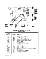
Страница 85: ...OK1 f t OK2 OSR i i STR 1 LA LB LC o r r l r l U l l J INU HL HM HS o o Figure 5 6 M2552K Revision 1 Circuit Card Layout T5 021 013087 01 5 15 iHS MM OS3 OS2 OS1 DSO TM JPl JP2 ...

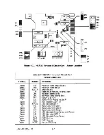
Страница 86: ...PCI AT CONF lOURATION MOVEABLE DM2 DM1 MOD Figure 5 7 M255J 54K Revision 2 Circuit Card Layout 5 16 T5 021 013087 01 ...

Страница 87: ...DM10M2 EIJ E J I 1 1 DSR STR PCIAT CONFIGURATION FDCED c 0 0 K 0 HS HM Figure 5 8 M255JK Revision J Circuit Card Layout TS 021 013087 01 5 17 i DS3 DS2 OS1 DSO TM i5M2 SM1 iD i RI c J FG ...

Страница 88: ... J8 12 MAl N PWB JI 20 Ie STEP SIDE 0 R W FINISH Y SIDE 0 COM J8 2 JI 22 WRITE DATA t Hi S DE 0 ERAS E J8 1 0 L I n1 lJ T S DE I S H LO b J8 8 JI 24 R TE GATE rmr A _____ S IDE I Rl W SAR T __ _b J8 3 JI 26 TRAc IC 00 SIDE I R W FINISH J8 11 Wy L S DE I C 0 M o J8 1 JI 28 t WRITE PROTECT IDE I ERASE Ja s JI 30 READ DATA L I m J J8 7 L _________________ __ JI 32 SIDE ONE SELECT o _ a t i _ HGE fo S...

Страница 89: ..._4 DAJ MAI l4WK 2 MAI I WA 5 I 4 I I f TS 021 013087 01 15 r l I I 2 I I 1 I L ____ J OKI OK2 r I I l Ir l __ _ j IK i o 30 I liOV L2 JP I 1 Cfl J 5V II C2 RESEIIU 0 04 IHUSUHLO 6 OS3 G8 INOEX to DSO OSI 14 CS2 fItOTOft ON 8 CIA ST P 22 WO WG 2S TOO Z8Wf 30 RO 32 51 34 ROY OCHG ri D GWO peA II PCB II JA2 5259 J2 5290 Figure 5 10 M2552K Revision l Schematic Diagram 5 19 ...

Страница 90: ...5 20 T5 021 013087 01 ...

Страница 91: ...0130B7 01 5Tr _4 II tfuT Of lJ H CUI04 rr q Z1Ot 1 2 4K _ R4l 8 t v 11K X on r rcfrl 4K 333 2700 qt l rl 2 r 6QoIH V X 1 4MHz oA3 MAI l4WA 4 I I I e t r oT I 2 I I I I I I lo 1 L ____ J fl ir j 4 1J4 I J I I 1 I I I 1 I L ______________ JI I HlYlSP 4 INUStlHlO J 0I on INDtX 10 OSO 12 051 14 CSI Il101 11 OIW 0 2DSlV t2 NO 24WQ ZllOO J II wp XI RO II 34 RIT r 1 33 GHO PCA II JA2 S20BB PCB 1 J2 S242B...

Страница 92: ...5 22 TS 021 013087 01 ...

Страница 93: ...It I I 1 6 I t Z l j r 1 t _ i JJ7 l 4 _ 1 J J9 I Q t v c R ltf 6M 1 M l L R64 4 7K t 1 Out r TP3 I I r 5M2 I SMI I I I IC1b L r t lfiL 13C r _ J in t h _y_ _t _ t_ I 5 1Sr iJ300 It It 1 i __ _t r r r h I as II r j I I I l i I I I I I STPMI I L ______________ II 5 It e i 4 3 Z c try 15 I 6 5 1t lZ D lC P 3 on r I RAI 1500_8 It It U FG 2 f11 LI I 12 1 II V 2 OV l2 DC POWER Jf 3 SUPPLy OV 1 1 U 0 lI...

Страница 94: ......
Отзывы:

Похожие инструкции для M255XK