6
3.2 Chip Select (JP508)
CS
Jumper setting
Description
CS0
ON (closed 1-2)
ULB-Interface Chip-Select 0
CS1
ON (closed 3-4)
ULB-Interface Chip-Select 1
CS2
ON (closed 5-6)
ULB-Interface Chip-Select 2
CS3
ON (closed 7-8)
ULB-Interface Chip-Select 3
CS4
ON (closed 9-10)
ULB-Interface Chip-Select 4
CS5
ON (closed 11-12)
ULB-Interface Chip-Select 5
CS6
ON (closed 13-14)
ULB-Interface Chip-Select 6
3.3 Define graphic controller Operating Mode (JP201, JP202, JP203)
Up to four Jasmine devices can be join one chip select. The size and location of configuration for every
Jasmine is fixed. The size is set to 64 kByte for every Jasmine and the location are specified by Mode
Jumpers (JP201, JP202).
Jasmine number
JP202
JP201
Jasmine 0
2-3
2-3
Jasmine 1
2-3
1-2
Jasmine 2
1-2
2-3
Mode1-0
Jasmine 3
1-2
1-2
Jasmine can also act as a 16Bit device from MCU’s point of view. The data mode can be set by Jumper
JP203.
JP203
Description
1-2
32 Bit data mode
Mode2
2-3
16 Bit data mode
It is possible to invert the RDY signal (Mode3 = 1). The RDY signal is not inverted with the application of
the CPU-Module (Mode3 = 0).
JP204
Description
Mode3
5-6
RDY not inverted
Содержание JASMINE
Страница 2: ...2 History Revision Date Comment V1 0 07 03 01 New Document ...
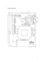
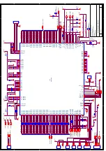
Страница 11: ...11 4 Schematics and Drawings ...

