15
Tubing
Suction Line Selection
Purpose of the suction line is to return superheated
vapor to the condensing unit from the evaporator.
Proper suction line sizing is important because it plays
an important role in returning oil to the compressor to
prevent potential damage to the bearings, valves, and
scroll sets. Also, an improperly sized suction line can
dramatically reduce capacity and performance of the
system. The procedure for selecting the proper suc-
tion line is as follows:
• The total amount of suction line needed
• Add all of the equivalent lengths associated with
DQ\ÀWWLQJVRUDFFHVVRULHVXVLQJWKHWDEOHRQSUHYL
-
ous page.
$GGWKHWRWDOOHQJWKDQGÀWWLQJSUHVVXUHGURS7KLV
will equal your total equivalent length.
• Reference Table 2 to verify that the calculated
equivalent length falls within the compatibility region
of the chart.
• Verify Table 3 to verify the capacity difference is
compatible with the application.
Refrigerant Migration During
Off Cycle
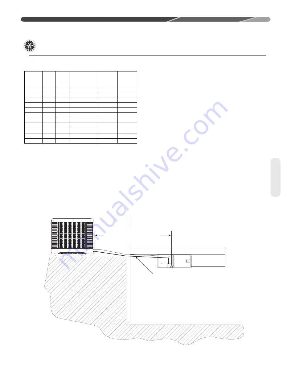
Long line set applications can require a consider-
able amount of additional refrigerant. This additional
refrigerant needs to be managed throughout the entire
ambient operating envelope that the system will go
through during its life cycle. Off-Cycle migration is
where excess refrigerant condenses and migrates to
the lowest part of the system. Excessive build-up of
refrigerant at the compressor will result in poor reli-
ability and noisy operation during startup. This sec-
tion demonstrates the required accessories and unit
FRQÀJXUDWLRQIRUGLIIHUHQWDSSOLFDWLRQV
OUTDOOR UNIT LEVEL OR NEAR LEVEL TO INDOOR SECTION LINE SET
LIQUID LINE.
ST-A1219-01-01
IDEALLY, LINE SET SLOPES AWAY
FROM OUTDOOR. VERIFY
SUB-COOLING PRIOR TO
THROTTLEING DEVICE, INSULATED
REFERENCE TABLE 2 FOR
MAXIMUM LENGTH LIMITATIONS
15 SEER Single Stage Heat Pump
!
18
C
J
ZP1
K
E-PFV-13R
21
N
24
A
J
ZP21K5E-PFV-13R
21
N
30
A
J
ZP25K5E-PFV-13R
25
N
36
A
J
ZP31K6E-PFV-130
21
N
42
A
J
ZP36K5E-PFV-13R
42
N
48
A
J
ZP40K6E-PFV-130
42
N
60
A
J
ZP49K6E-PFV-130
42
Y
36
A
C
ZP31K6E-TF5-130
21
N
42
A
C
ZP36K5E-TF5-13R
42
N
48
A
C
ZP40K6E-TF5-130
42
Y
60
A
C
ZP49K6E-TF5-130
42
Y
Factory
Installed
CCH
Voltage
Compressor
Name Plate
Oil Charge
(oz)
Model #
Capacity
Major
Series
INSTALLATION
Interconnecting Tubing (cont.)
Содержание FO14R Series
Страница 44: ...44 FOR SINGLE PHASE WITH PSC FAN MOTORS WIRING DIAGRAMS Wiring Diagrams ...
Страница 45: ...45 Wiring Diagrams WIRING DIAGRAMS 3 PHASE 208 230V MODELS ...
Страница 46: ...46 Wiring Diagrams WIRING DIAGRAMS FOR 3 PHASE 460 575V ...
Страница 48: ...48 ...


