


CHAPTER 5
Extension Configuration
Installing Power, Ground, and Alarm Cables
FNC-7500-0061-200
Issue 1, May 2009
FLASHWAVE 7500 Release 6.1
Equipment Installation
5-24
Fujitsu and Fujitsu Customer Use Only
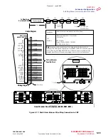
5.10
Installing Power,
G
round, and Alarm Cables
This procedure provides instructions for installing power, ground, and alarm cabling for
standard rack configurations.
N
O
.
S
UBPROCEDURE
P
A
G
E
It includes the following subprocedures:
P
r
o
c
e
d
u
r
e
5.10.1
Reference Material
The cables and cable harnesses are listed in
.
Note:
Connections to the shelf power terminal strip should use copper conductors only.
Table 5-1: Power,
G
round, and Alarm Cable Connections
(Extension Configuration)
Part Number
Use
Description
Term Type
Wire
G
auge
HA15B-0001-C413
–48 V DC and
ground
5-wire rack/shelf power harness,
one set per shelf
10 AWG crimp
lugs
10 AWG
HA660-1106-T003
Rack alarms
6-connector daisy-chained alarm
harness, one connector per shelf
(CNA through CNF), one harness
per rack
D-sub 25-pin,
terminates with
wire-wrap at CBP
24 AWG
HA660-1102-T015
Shelf alarms
Alarm cable from rack alarm cable
connector to shelf backplane alarm
connector, one per shelf
D-sub 25-pin,
CN1 at rack
alarm end, CN2
at shelf alarm end
24 AWG
PC15L-0001-C045
Frame ground
Frame ground stranded wire cable
from rack to CBP, one per rack
Terminal lugs,
both ends,
installed
6 AWG, stranded
Revision 1, June 2009
Содержание FLASHWAVE 7500
Страница 8: ...Revision 1 June 2009 ...
Страница 10: ...Revision 1 June 2009 ...
Страница 16: ...Revision 1 June 2009 ...
Страница 362: ...Revision 1 June 2009 ...
Страница 386: ...Revision 1 June 2009 ...