CHAPTER 3
Small Configuration
Installing Cables
3-117
FLASHWAVE 7500 Release 6.1
Equipment Installation
Fujitsu and Fujitsu Customer Use Only
FNC-7500-0061-200
Issue 1, May 2009
3.19.7
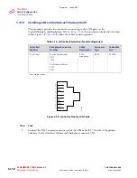
Installing OSS Cable (Optical Shelf)
This procedure provides instructions for assembling the OSS cable and installing it on the
Optical shelf backplane (CN12).
lists pertinent information for this
cable.
shows the cable connector pinouts.
Step
Task
1
Connect the cable to shelf backplane connector CN12 (Optical shelf ). See
.
2
Connect the other end of the cable to the appropriate router or hub.
Note:
The 21-094-xxx cable can also be used to connect a PC to the TERM2 Ethernet port on the
Optical shelf front panel.
Note:
The OSS port has automatic cable-detect capability to properly function with both crossover
and straight cables.
This procedure is complete.
Table 3-13: OSS Cable Information
(Small Configuration)
Cable Part
Number
Backplane
Connector
Number
Cable Description
Connector
Type
Cable Wire
Size
21-332-xxx or
21-094-xxx
a
a
xxx = length in feet
CN12
Ethernet connection
8-pin RJ-45
24 AWG
Figure 3-88: Connector Pinouts, OSS Cable
1
2
3
4
5
6
7
8
TXP
TXN
RXP
RXN
m1
71
4a
u_
1
Revision 1, June 2009
Содержание FLASHWAVE 7500
Страница 8: ...Revision 1 June 2009 ...
Страница 10: ...Revision 1 June 2009 ...
Страница 16: ...Revision 1 June 2009 ...
Страница 362: ...Revision 1 June 2009 ...
Страница 386: ...Revision 1 June 2009 ...


