background image

2-25

2.3 Installing the Scanner Driver and Application

2

IN
ST
ALLA

TION AND C

O

NN

EC

TION

S

Confirming Installation

1.

Set documents on the Hopper.

For details on how to load documents, refer to the "1.2 Loading Documents on 
the ADF for Scanning" in the fi-4860 Operator’s Guide provided in the User 
Manual CD-ROM.

2.

Start ScandAll21

Select [Start] - [Programs] - [Scanner Utility for Microsoft Windows] - [ScandAll 
21].

3.

Specify the scanner to use

Select [Select Source...] from the [Scan] menu of ScandAll 21.

ATTENTION

To finish the installation, it may be necessary to restart your computer. 
Follow the instructions in the window.

Содержание fi-4860C

Страница 1: ...Installation Guide fi 4860C Image Scanner P3PC E177 04EN ...

Страница 2: ......

Страница 3: ...manual are as follows 1 SCANNER BASICS This chapter describes the contents of the scanner package part names and operator panel operation 2 INSTALLATION AND CONNECTIONS This chapter describes how to install and connect the scanner to a PC and how to install the scanner application software The Operator s Guide is also stored on the User Manual CD ROM The guide includes operation and daily care for...

Страница 4: ...OMMON PROBLEMS This chapter describes how to remedy document jams other troubles items to check before contacting the agent where you bought the scanner and how to check device labels 6 ADF DOCUMENT SPECIFICATIONS This chapter describes the types of documents which can be scanned with this scanner 7 OPERATOR PANEL MENUS This chapter describes Setup mode and Test mode 8 OPTIONS This chapter describ...

Страница 5: ...to radio or television reception which can be determined by turning the equipment off and on the user is encouraged to try to correct the interference by one or more of the following measures Reorient or relocate the receiving antenna Increase the separation between the equipment and receiver Connect the equipment into an outlet on a circuit different from that to which the receiver is located Con...

Страница 6: ...Berechtigung zur Überprüfung der Serie auf Einhaltung der Bestimmungen eingeräumt Maschinenlärminformationsverordnung 3 GS GV 18 01 1991 Der höchste Schalldruckpegel beträgt 70 dB A order weniger gemäß ISO 7779 International ENERGY STAR Program As an ENERGY STAR Partner PFU LIMITED has determined that this product meets the ENERGY STAR guidelines for energy efficiency The International ENERGY STAR...

Страница 7: ...ications PFU LIMITED assumes no liability whatsoever for damages arising from use of this product by the user in high safety applications and for any claims or compensation for damages by the user or a third party About the use of mercury The scanner lamps contain mercury To avoid unexpected injury read the followings carefully Doing following actions may result in serious personal injuries Do not...

Страница 8: ...ws 95 Microsoft Windows 95 operating system Windows 98 Microsoft Windows 98 operating system Windows Me Microsoft Windows Millennium Edition operating system Windows NT 4 0 Microsoft Windows NT 4 0 Server operating system Microsoft Windows NT 4 0 Workstation operating systemoperating system Windows 2000 Microsoft Windows 2000 Professional operating system Windows XP Microsoft Windows XP Profession...

Страница 9: ...by statements of any kind in this manual its updates or supplements whether such errors are omissions or statements resulting from negligence accidents or any other cause PFU LIMITED further assumes no liability arising from the application or use of any product or system described herein nor any liability for incidental or consequential damages arising from the use of this manual PFU LIMITED disc...

Страница 10: ...and safe place so that it can be easily referred to during use of this product Warning Indications Used In This Manual This manual uses the following indications to ensure safe and correct use of this product and to prevent possible danger and injury to the operator and other persons WARNING This indication alerts operators to an operation that if not strictly observed may result in severe injury ...

Страница 11: ...and ScandAll 21 image capturing software FUJITSU ISIS scanner driver QuickScan image capturing software and Adobe Acrobat ATTENTION This symbol alerts operators to particularly important information Be sure to read this information HINT This symbol alerts operators to helpful advice regarding operation A TRIANGLE symbol indicates that special care and attention is required The drawing inside the t...

Страница 12: ...nds Do not damage the AC cable Use only specified AC cables and connector cables Do not touch the power plug with wet hands Doing so might cause electric shock A damaged AC cable may cause fire or electric shock Do not place heavy objects on AC cables or pull bend twist heat damage or modify AC cables Also do not use damaged AC cables or power plugs and AC cables or power plugs when the wall socke...

Страница 13: ... to multiple power strips Wipe off any dust from metal parts on the power plug or metal fittings with a soft dry cloth Accumulated dust might cause fire or electric shock Do not install the scanner in locations subject to oil smoke steam humidity and dust Doing so might cause a fire or electric shock If you detect heat coming from the device or detect other problems such as smoke strange smells or...

Страница 14: ...ent with paper clips or staples Do not splash or allow the scanner to get wet If foreign objects water small metal objects liquids etc get inside the scanner immediately turn off the scanner and disconnect the power plug from the power outlet then contact the store where you bought the scan ner or the Maintenance Service Center Pay particular attention to this warning in households where there are...

Страница 15: ...vel surface Do not install the scanner on unstable surfaces Install the scanner on a level surface that is free of vibration to prevent it from falling Install the scanner on a strong surface that will support the weight of the scanner and other devices Firmly insert the power plug into the power outlet as far it can go Do not block the ventilation ports Blocking the ventilation ports generates he...

Страница 16: ...ure to disconnect the power plug from the power outlet and disconnect data cables Also make sure that the floor is free of obstructions Install the scanner away from strong magnetic fields and other sources of interference Also protect the scanner from static electricity as this might cause the scanner to malfunction Do not use aerosol sprays to clean the scanner Aerosol sprays cause dirt and dust...

Страница 17: ...used for a long period of time be sure to disconnect the power plug from the power outlet for safety Do not install the scanner in the direct sunlight or near heating apparatus Doing so might cause excessive heat to build up inside the scanner causing fire or scanner trouble Install the scanner in a well ventilated location This scanner is heavy 99lbs 45kg When you carry the scanner ensure that ad...

Страница 18: ...tp www fel fujitsu com FUJITSU DEUTSCHLAND GmbH Frankfurter Ring 211 80807 München Germany Phone 49 89 323 78 0 Fax 49 89 323 78 100 Website http www fdg fujitsu com E mail hotline_scanner fdg fujitsu com FUJITSU ITALIA S p A Via Nazario Sauro 38 20099 Sesto San Giovanni Milan Italy Phone 39 02 26294 1 Fax 39 02 26294 201 Website http www fis fujitsu com E mail mbarondi fis fujitsu com FUJITSU ESP...

Страница 19: ...a Phone 82 2 3787 6159 Fax 82 2 3787 6164 Website http kr fujitsu com E mail webmaster fkl fujitsu co kr FUJITSU MALAYSIA SDN BHD Level 1 3505 Jalan Teknokrat 5 63000 Cyberjaya Malaysia Phone 60 3 8318 3700 Fax 60 3 8318 8700 Website http my fujitsu com FUJITSU PHILIPPINES INC 2 F United Life Building 837 A Arnaiz Avenue Pasay Road Legaspi Village Makati City 1229 Philippines Phone 63 2 812 4001 F...

Страница 20: ... xviii ...

Страница 21: ... 13 Installing the Scanner Driver and Application 2 17 APPENDIX 1 MESSAGES OF OPERATOR PANEL AP 1 Massages of Scaner Operation Status AP 1 Error messages Temporary errors Check LED blinking AP 5 Alarm messages Hardware errors Check LED lighting AP 9 APPENDIX 2 CONSUMABLES AND REPLACEMENT CYCLE AP 14 APPENDIX 3 TROUBLESHOOTING AP 15 APPENDIX 4 CLEARING DOCUMENT JAMS AP 17 Removing jams from the hop...

Страница 22: ... xx ...

Страница 23: ...1 1 1 SCANNER BASICS This chapter describes how to prepare the scanner before use 1 1 Checking the Contents of the Scanner Package 1 2 1 2 Names and Functions of Parts 1 3 1 3 Operator Panel 1 6 ...

Страница 24: ...e included in the package If any parts are missing or defective contact to the distributer where you purchased the scanner from Please handle the scanner and the accessories with care Scanner and Accessories Scanner Power cable x1 User Manual CD ROM Setup CD ROM Adobe Acrobat 5 0 CD ROM Installation Guide This manual FUJITSU ISIS Quick Installation Guide fi X XX X XX XX XX XX X ...

Страница 25: ...3 1 2 Names and Functions of Parts 1 SCANNER BASICS 1 2 Names and Functions of Parts This section describes the names of parts and their functions Units 13 1 2 3 4 5 7 8 9 10 11 12 14 19 6 15 16 18 17 19 ...

Страница 26: ...e The pad assy is mounted on 9 Pad Assy Separates top page from document stack 10 Upper transport unit Opens for easy access 11 Lever Used to open the Upper transport unit 12 Stacker Document exit tray 13 Stopper Used to stop documents as they exit into the stacker 14 Stacker extension Used to support long documents 15 Main line switch Controls supply of line power to the scanner 16 Power inlet Fo...

Страница 27: ... 5 1 2 Names and Functions of Parts 1 SCANNER BASICS Assemblies Lamp Lamp Lamp socket cover Guide plate Brake roller unit Pick roller unit Lamp unit Removable glass sheetguide Lamp socket cover PAD Assy ...

Страница 28: ...perator Panel 1 3 Operator Panel 1 The operator panel is located at the Upper right hand side of the scanner The panel consists of an LCD display 16 characters x 2 line LEDs and buttons Arrangement Power button ...

Страница 29: ... on or is blink ing Enter Used for setup or test mode Exit Used for setup or test mode Returns LCD display to Ready status Previous Used for setup or test mode Displays the previous menu item when this button is pushed Next Used for setup or test mode Displays the next menu item when this button is pushed Used for setup or test mode Changes the setting of the selected item Used for setup or test m...

Страница 30: ...are alarm is detected Lights out when button is pushed except initial errors Blinks when an equipment error occurs Paper jam or Double feed is detected Press Stop button to clear the error and the LED lights out In the case of Paper jam when the document is removed and the Upper transport unit is closed the LED lights out automatically LCD Function Displays the scanner sutatus and error messages ...

Страница 31: ...r K Fig 1 Simultaneously press the both Left and Right button for at least one second to switch to the Life counter panel display as shown bellow Batch counter L Life counter K Fig 2 To return from Fig 2 to Fig 1 press the both Left and Right button for at least one second d a x x x x x x x x x x e R x y d a x x x x x x x x e R y x x x x x ...

Страница 32: ...ed off The counter can be used for checking the number of scanned documents per day Abrasion counter The abrasion counter counts the accumulated number of scanned sheets This counter is increased by one per sheet scanned It is used for checking the cleaning cycle or the parts replacement cycle Refer to Chapter7 OPERATOR PANEL MENUS of the Opelator s Guide included in User Manual CD ROM about how t...

Страница 33: ...g system Windows Me Microsoft Windows Millennium Edition operating system Windows NT 4 0 Microsoft Windows NT 4 0 Server operating system Microsoft Windows NT 4 0 Workstation operating systemoperating system Windows 2000 Microsoft Windows 2000 Professional operating system Windows XP Microsoft Windows XP Professional operating system and Microsoft Windows XP Home Edition operating system 2 1 Insta...

Страница 34: ...f scanner 1 Move the scanner to the installation area Refer to the Operator s Guide stored on the User Manual CD ROM about the dimensions of the scanner and the space required for its installation ATTENTION Move the scanner with more than two people as it weights approximately 99 lbs 45 Kg ATTENTION When you move scanner grab it at its bottom ...

Страница 35: ...ace cable and a SCSI card are required Use the following SCSI card to connect to PC Use of other SCSI card may cause unstable scan operations If you use ADAPTEC SCSI card 29160 39160 make sure you install the proper drivers and updates as described below Recommended SCSI card Recommended interface cable ADAPTEC SCSI card 29160 ADAPTEC ACK LVD CBL KIT ADAPTEC SCSI card 39160 ADAPTEC ACK 68V 68HD LV...

Страница 36: ...ress If you use FUJITSU TWAIN32 Version9 x you do not need to install the ASPI driver For Windows 98 Windows NT 4 0 Windows Me Windows 2000 and Windows XP http www adaptec com worldwide support drivers_by_product html sess no cat Product ASPI 4 70 For Windows 95 http www adaptec com worldwide support driverdetail html sess no filekey aspi32 exe If you use Windows XP follow the procedure below besi...

Страница 37: ...ide support drivers_by_product html sess no cat Product ASC 39160 ATTENTION When connecting the SCSI interface cable be sure to first connect the SCSI interface cable then turn on the power of the scanner and the PC ATTENTION Connect the scanner so that it is the last device on the SCSI daisy chain ATTENTION The SCSI card and SCSI interface cable need to be purchased sepa rately HINT If the file a...

Страница 38: ...e to the PC HINT The factory default setting for the scanner s SCSI ID is No 5 If the SCSI ID of another SCSI device is set to the same ID either change the scanner s SCSI ID or change the SCSI ID of the other SCSI device For details on how to change the SCSI ID refer to the Chapter 7 OPER ATOR PANEL MENUS of the Operator s Guide included in the User manual CD ROM Interface connecter Back side ...

Страница 39: ... FUJITSU ISIS Scanner Driver For FUJITSU TWAIN32 Scanner Driver Preparation Confirm the following items before starting to install the application Prepare the Setup CD ROM at hand Do not insert the Setup CD ROM into the CD drive yet Confirm that the scanner is correctly connected to your PC Uninstall any older versions of the FUJITSU TWAIN 32 driver if it has already been installed There are two t...

Страница 40: ...generally comes with SCSI board products Installing the FUJITSU TWAIN32 Scanner Driver 1 Turn on the scanner Press the side of on the Main line switch Then press the Power button on the Operator panel When the power is supplied the green LED on the Operator panel lights HINT Windows XP screenshots are used in this section The windows and oper ations may slightly vary depending on your OS Main line...

Страница 41: ...anner is detected automatically Found New Hardware Wizard or Add Remove Hardware Wizard dialog box will appear ATTENTION When using Windows NT 4 0 Windows 2000 or Windows XP log on as a user with Administrator privileges privileges of the administrator of your PC Otherwise the installation will not be completed correctly Power Button ...

Страница 42: ... Wizard window 4 Insert the Setup CD ROM into the CD drive SETUP DISK START UP SCREEN appears 5 Click INSTALL PRODUCTS ATTENTION This screen may not appear if the Autoplay setting of your PC is OFF In this case run Install exe in this CD ROM directly by the Explorer or My Computer ...

Страница 43: ...2 21 2 3 Installing the Scanner Driver and Application 2 INSTALLATION AND CONNECTIONS 6 Click TWAIN Driver on the window below ...

Страница 44: ...ENTION Depending on the OS the following operations may be necessary For Windows 98 When a request for inserting the CD ROM of Winows 98 appears insert it into the CD drive and click the OK button For Windows 2000 When Digital Signature not Found appears click Yes For Windows XP 1 When Found New Hardware Wizard appears confirm that the Setup CD ROM is set in the CD drive then click the Next button...

Страница 45: ...r driver you can capture images using a FUJITSU image scanner fi series product 1 Insert the Setup CD ROM into the CD drive SETUP DISK START UP SCREEN appears 2 Click INSTALL PRODUCTS 3 Click ScandAll 21 on the window below ATTENTION When using Windows NT 4 0 Windows 2000 or Windows XP log on as a user with Administrator privileges privileges of the administrator of your PC Otherwise the installat...

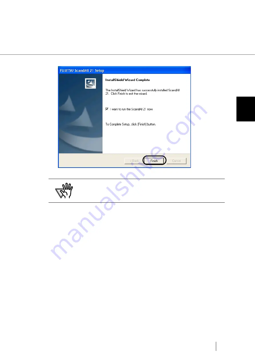
Страница 46: ... and Application 4 Select a language used for installation on Choose Setup Language window and click OK 5 Install the application following the instructions on the window 6 When the InstallShield Wizard Complete window appears click Finish ...

Страница 47: ...ing Documents on the ADF for Scanning in the fi 4860 Operator s Guide provided in the User Manual CD ROM 2 Start ScandAll21 Select Start Programs Scanner Utility for Microsoft Windows ScandAll 21 3 Specify the scanner to use Select Select Source from the Scan menu of ScandAll 21 ATTENTION To finish the installation it may be necessary to restart your computer Follow the instructions in the window ...

Страница 48: ...he dialog box appeared 5 Select To View from the Scan menu 6 Set scanning resolution document size etc on the TWAIN driver window for setting details of scanning and click the Scan button HINT For Windows 98 Windows Me Windows 2000 Windows XP FUJITSU fi 4860CEAdij For Windows 95 Windows NT 4 0 FUJITSU TWAIN32 ...

Страница 49: ...d Application 2 INSTALLATION AND CONNECTIONS 7 Documents are scanned and the scanned images are displayed on the ScandAll 21 window HINT For details on TWAIN driver refer to the FUJITSU TWAIN32 Scanner Driver Help provided on the Setup CD ROM ...

Страница 50: ...items before starting to install the application Prepare the Setup CD ROM at hand Do not insert the Setup CD ROM into the CD drive yet Confirm that the scanner is correctly connected to your PC Installing the FUJITSU ISIS Scanner Driver 1 Turn on the scanner Press the side of on the Main line switch HINT For details on how to connect the scanner refer to 2 2 Connecting the Scanner on page 2 13 HIN...

Страница 51: ...anner Driver and Application 2 INSTALLATION AND CONNECTIONS Then press the Power button on the Operator panel When the power is supplied the green LED on the Operator panel lights Main line switch Back side Power on Power Button ...

Страница 52: ... 4 Insert the Setup CD ROM into the CD drive SETUP DISK START UP SCREEN appears ATTENTION When using Windows NT 4 0 Windows 2000 or Windows XP log on as a user with Administrator privileges privileges of the administrator of your PC Otherwise the installation will not be completed correctly ATTENTION This screen may not appear if the Autoplay setting of your PC is OFF In this case run Install exe ...

Страница 53: ...2 31 2 3 Installing the Scanner Driver and Application 2 INSTALLATION AND CONNECTIONS 5 Click INSTALL PRODUCTS 6 Click ISIS Driver on the window below ...

Страница 54: ...ill be completey restarted Now the installation of the scanner driver is completed ATTENTION Depending on the OS the following operations may be necessary For Windows 98 When a request for inserting the CD ROM of Winows 98 appears insert it into the CD drive and click the OK button For Windows 2000 When Digital Signature not Found appears click Yes For Windows XP 1 When Found New Hardware Wizard a...

Страница 55: ...e FUJITSU ISIS scanner driver you can capture images using a FUJITSU image scanner fi series product 1 Insert the Setup CD ROM into the CD drive SETUP DISK STARTUP SCREEN appears 2 Click INSTALL PRODUCTS ATTENTION When using Windows NT 4 0 Windows 2000 or Windows XP log on as a user with Administrator privileges privileges of the administrator of your PC Otherwise the installation will not be comp...

Страница 56: ...2 34 2 3 Installing the Scanner Driver and Application 3 Click QuickScan PROTM Trial on the window below 4 Install the application following the instructions on the window ...

Страница 57: ...tion following the instructions on the window ATTENTION QuickScan Pro included in the Setup CD ROM is an evaluation version For further use after expiration of the evaluation period up to 30 launches it is necessary to purchase a fully functional version of QuickScan Pro When you install the evaluation version do not change the Serial Number already displayed ...

Страница 58: ...lows 1 Start QuickScan ProTM From Start menu select Programs QuickScan QuickScan 2 Select Select Scanner from Scan menu in QuickScan ProTM And select fi 4860C from the list of Scanner and then click OK button 3 Select Preview Settings from the Scan menu Set the scan resolution paper size and other scanning conditions and then click OK ...

Страница 59: ...canning in the fi 4860C Operator s Guide on the User Manual CD ROM 6 Select Preview Scan from the Scan menu And then the document is scanned If the scanning is completed without any troubles the installation was performed successfully HINT Refer to QuickScan Overview or QuickScan Help for information about QuickScan functions and operations On the Start menu point to Pro grams QuickScan and click ...

Страница 60: ...displayed 2 The following window appears Click the Next button HINT Adobe Acrobat is required for displaying the manuals stored on the User Manual CD ROM It is also possible to set Adobe Acrobat to display scanned images working together with the scanner Installation of Adobe Acrobat is not necessary if it is already installed on your PC ATTENTION If the Adobe Acrobat 5 0 AutoPlay screen is not di...

Страница 61: ...39 2 3 Installing the Scanner Driver and Application 2 INSTALLATION AND CONNECTIONS 3 The following window appears Click the Acrobat 5 0 button then click the Install Adobe Acrobat 5 0 button shown below ...

Страница 62: ...tup window appears Install Adobe Acrobat by following the instructions in the window HINT For details on installation of Adobe Acrobat 5 0 read the description that is displayed by clicking the Before you install button in the screen at Opera tion 3 For details on how to use Adobe Acrobat 5 0 refer to Adobe Acro bat 5 0 Help ...

Страница 63: ...sor Not Ready status Resetting the hopper Not Ready status Waiting to initialize inter face board Low ink alarms preparing the print car tridge At power on W a m i n g p N o j e c t a p p e r r u w E i n g C h e c k s s o r e n W a m i n g p N o r u w i n g e s e t h e p p o W a m i n g p N o r u w R t i n g r W a t n R e a i I F g i d y l e s p a e r e p a a n e w I n k p r e P r e l e s p a e r ...

Страница 64: ...have disappeared and only the Power LED lamp stays lit the scanner is in the Low power mode ATTENTION To reactivate the scanner from the Low power mode perform one of the following operations Press any button except power button on the Operator Panel Set documents on the Hopper Send a command from PC r e a n e p R e a d r e I n k i n x x x x P w N o w g R e a d i n x x x x N o w g ...

Страница 65: ...d detection state press the button The upper row of this message Double Feedxxxxx will blink HINT xxxx upper shows the value of the Batch counter xxxxxxxx lower shows the value of the Abration or Life counter Double feed error Scanning The following message is displayed while the scanner is scanning continu ously and a double feed has been detected by checking paper thickness When a double feed de...

Страница 66: ...kness has been detected To abort the double feed detection state press the button The upper row of this message Double Feedxxxxx will blink HINT xxxx upper shows the value of the Batch counter xxxxxxxx lower shows the value of the Abrasion or Life counter D u e l o b F e d x e e a d y x x x x x x R x x x x x x ...

Страница 67: ...ocuments on the hopper for re scanning To clear this message press the button HINT The check LED does not blink when the Hopper empty errors at Double feed HINT xxxx shows the value of the Batch counter Paper Jam The following message is displayed if a document is jammed in the ADF Refer to the Operator guide included in User manual CD ROM for remov ing the jammed documents HINT One of 1 8 is disp...

Страница 68: ...feed is detected by paper thickness check by length check The following message is displayed when a double feed is detected by paper length check Mis pick The following message is displayed when a document is not sent from the hopper to the ADF HINT The Check LED does not blink when a Mis pick error occurs Pick overrun The following message is displayed when a document is sent from the hop per to ...

Страница 69: ...et The following message is displayed when the Pick roller unit is not set cor rectly When there are no documents on the hopper Pick unit not set The following message is displayed when the Pick roller unit is not set cor rectly during scanning Brake roller not set The following message is displayed when the scan operation is performed while the Brake roller unit is not set correctly I r u l g r e...

Страница 70: ...on counter value exceeds the setting value for displaying the consumables replacement mes sage Print cartridge not set The following message is displayed when the Print cartridge is not installed in the fi 486PRFR front side Imprinter or to the fi 486PRRE back side Imprinter p S a r e a i o t n l o e r r l o r w n b s a A r o a n a r m l i N k n o I C r t a i d g e r P e r N k n o I C r t a i d g ...

Страница 71: ... the front side optical unit Optical alarm Back side The following message is displayed when an error occurs at the back side optical unit Motor fuse alarm Transport motor The following messages are displayed when the fuse of particular motors Transport motor Separation motor Pick motor Hopper motor blows out Separation motor Pick motor Hopper motor p c a i O t l A l r m a F o r n d e i t S p c a ...

Страница 72: ...e following message is displayed when the fuse for changing the Back ground of back side blows out Background alarm Front side The following message is displayed when the Background of front side can not be changed Background alarm Back side The following message is displayed when the Background of back side can not be changed o F n t r i d s e F s u e a l r m a l a m p a c k B i d s e F s u e a l...

Страница 73: ...rs due to a dirt on the sensor HINT xxxx indicates the sensor name SUS SF0 SA4 etc Sensor alarm The following message is displayed when a sensor error occurs HINT xxxx indicates the sensor name SUS SF0 SA4 etc Temperature alarm The following message is displayed when the temperature inside the scan ner exceeds the standard temperature H p r e o p o e r v r u n n o n s e S C r o A l r m a o t l r e...

Страница 74: ...ccurs when accessing the VDCC area MDC timeout The following message is displayed if an error occurs when accessing the MDC area Dither Gamma Read Write alarm The following message is displayed if an error occurs when accessing the Dither Gamma RAM Temporary memory Read Write alarm The following message is displayed if an error occurs during accessing the temporary memory p e o w P s r u y p l r e...

Страница 75: ...de Imprinter Command alarm The following message is displayed when an error occurs in the command sequence from PC MDC command timeout 1 MDC command timeout 2 SDC command Sequence alarm MDC response alarm SCSI response time out l D C M o w d n d o a E o r r r P e r I p n t i m r e A r a r m l P s o I p n t i m r e A r a r m l t C m n a o m d r E o r 1 r C m n a o m d r E o r 2 r C m n a o m d r E ...

Страница 76: ...ment cycle is based on the printing on Letter A4 woodfree paper or wood containing paper documents 64 g m2 The replacement cycle may differ due to paper quality print density or paper type For the purchase of the consumables please contact the FUJITSU scanner dealer where you pur chased your scanner Descriptions Part No Standard replacement cycle Lamp PA83950 0290 1 000 Hours 60 000minutes Pad ASS...

Страница 77: ...he fi 4860C Operator s Guide The scanned image is distorted and or not sharp Refer to Chapter 5 2 Troubleshooting Symptom6 of the fi 4860C Operator s Guide Vertical streaks appear in the scanned image Refer to Chapter 5 2 Troubleshooting Symptom7 of the fi 4860C Operator s Guide Check LED starts blinking right after power on Refer to Chapter 5 2 Troubleshooting Symptom8 of the fi 4860C Operator s ...

Страница 78: ...t recognized by PC automatically Refer to Chapter 5 2 Troubleshooting Symptom13 of the fi 4860C Operator s Guide Windows system gets unstable Refer to Chapter 5 2 Troubleshooting Symptom14 of the fi 4860C Operator s Guide ...

Страница 79: ... on the right front of the Upper transport and then raise it CAUTION Be careful not to get injured during jam removal When removing jammed documents be careful not to get your neckties or necklaces entangled inside the scanners The surface of the glass sometimes becomes hot during operation Take care not to get burned CAUTION Raise the Upper transport unit fully then lower the transport to engage ...

Страница 80: ...ransport unit fully to release the safety lock and then lower the transport unit carefully ATTENTION Staples and paper clips etc can cause document jams Make sure you check the document and the document transport path for obstructions before you start scanning again Remove staples and paper clips from the documents before you start scanning ADF upper sheet guide ADF release lever ...

Страница 81: ...ker 2 Pull up on the lever on the right front of the Upper transport and then raise it 3 Pull out the jammed document to the stacker 4 Lift the Upper transport unit fully to release the safety lock and then lower the transport unit carefully ADF upper sheet guide ADF release lever ...

Страница 82: ... mode The following screen appears Choose an appropriate setting based on the thickness of the document you are scanning and the error By pressing Right arrow button the LCD display changes items from 5 to 1 By pressing Left arrow button the LCD display changes items from 1 to 5 When the desired option appears press Enter button to select it 1 Document thickness Thick 2 Document thickness Medium t...

Страница 83: ...eed occurs frequently Mis pick or Docu ment jam occurs fre quently Thick Thick Strong Increase docu ment separation force Decrease docu ment separation force Medium Thick Medium Thick Medium strong Medium Medium Medium Factory default set ting Medium Thin Medium Thin Medium Easy Thin Thin Easy HINT The blinking item is the one selected Pick speed Mis pick occurs frequently Fast Factory default Dec...

Страница 84: ...AP 22 ...

Страница 85: ... Consumables Part No AP 14 replacement cycle AP 14 Contents 1 xviii Contents of the Scanner Package 1 2 Counter display 1 9 Abrasion counter 1 9 Batch counter 1 9 Life counter 1 9 F Fujitsu Group Offices 1 xvi G Guide plate 1 4 1 5 H Hopper 1 4 Hopper extension 1 4 I Imprinter cover 1 4 Installation and Connections 2 11 Installation Guide 1 2 Installing the Scanner 2 12 Installing the Scanner Driv...

Страница 86: ...4 Preface 1 viii R Regulatory Information 1 iii Removable sheet guide 1 5 S Safety Precautions 1 x Scanner Basics 1 1 Side guides 1 4 Stacker 1 4 Stacker extension 1 4 Stopper 1 4 T Third party slot TPS 1 4 U Upper transport unit 1 4 User Manual 1 2 2 12 ...

Страница 87: ...nts of this manual in whole or in part and copying of the scanner application is forbidden under the copyright law The contents of this manual are subject to change without notice PFU LIMITED is not liable whatsoever for any damages resulting from use of this scanner and procedures described in this manual profit due to defects and any claims by a third party ...

Страница 88: ......

Отзывы: