Kurzbeschreibung des Mainboards
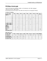
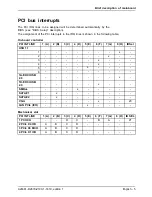
PCI-Bus-Interrupts
Welche PCI IRQ Lines zugeordnet werden, wird automatisch vom BIOS festgelegt
(siehe Beschreibung "BIOS-Setup").
Die Zuordnung der PCI-Interrupts zu den IRQ Lines
fi
nden Sie in der folgenden Tabelle:
On board controller
PCI INT LINE
1 (A)
2 (B)
3 (C)
4 (D)
5 (E)
6 (F)
7 (G)
8 (H)
IDSel
USB 1.1
-
1
-
-
-
-
-
-
-
x
-
2
-
-
-
-
-
-
x
-
-
3
-
-
-
-
-
x
-
-
-
4
-
-
-
-
-
x
-
-
-
5
-
-
-
-
x
-
-
-
-
6
-
-
-
-
-
-
-
-
-
1A-EHCI USB 2.0
-
-
-
-
-
-
-
x
-
1D-EHCI USB 2.0
-
-
-
-
-
x
-
-
-
SMBus
-
-
-
x
-
-
-
-
-
SATA #1
-
x
-
-
-
-
-
-
-
SATA #2
-
x
-
-
-
-
-
-
-
VGA
-
-
-
-
-
x
-
-
23
LAN PCIe (ICH)
-
-
-
-
x
-
-
-
-
Mechanical Slot
PCI INT LINE
1 (A)
2 (B)
3 (C)
4 (D)
5 (E)
6 (F)
7 (G)
8 (H)
ID SEL
1 PCI ICH
-
-
D
C
-
B
A
-
21
2 PCIe X4 ICH
A
B
C
D
-
-
-
-
-
3 PCIe X8 MCH
A
B
C
D
4 PCIe X1 ICH
A
B
C
D
-
-
-
-
-
A26361-D2679-Z100-1-7419, Ausgabe 1
Deutsch - 5


