6
Brocade 6545 Gen5 16-Gbps FC Switch Module Hardware Reference Manual
53-1003184-01
Hardware Description
1
Hardware Description
This section describes the physical Switch Module as shipped from the factory. For specifications,
such as installed memory, weight and physical dimensions, facility requirements, architectural
specifications, and regulatory compliance, refer to
Appendix A, “Brocade 6545 16 Gbps FC Switch
Module Specifications”
Front panel
Externally accessible ports and LEDs are on the port side of the Switch Module. The front panel
faces out when the Switch Module is inserted in the
I/O bay of the Blade Server chassis
.
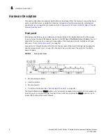
Figure 1
details the front panel. For a complete description of the locations and interpretations of these
LEDs, see
“Interpreting LED activity”
on page 38.
Access the I/O module handle at the front of the port side of the Switch Module. By pressing the
handle’s release latch, you can open the handle to remove and insert the unit from the Blade
Server chassis.
FIGURE 1
Front panel view
1. Module status indicator
2. Health indicator
3. Module Locator
4. Port status indicators (See
“Interpreting LED activity”
on page 38.)
The Switch Module has a Reset button, which is a small, recessed micro-switch that is accessed by
inserting a pin (or an object of similar size) in the small hole. Depress the Reset button for up to
5 seconds to reboot the Switch Module.
Содержание Brocade 6545 Gen5
Страница 1: ...53 1003184 01 16 June 2014 Brocade 6545 Gen5 16 Gbps FC Switch Module Hardware Reference Manual ...
Страница 12: ...xii Brocade 6545 Gen5 16 Gbps FC Switch Module Hardware Reference Manual 53 1003184 01 ...
Страница 64: ...52 Brocade 6545 Gen5 16 Gbps FC Switch Module Hardware Reference Manual 53 1003184 01 Long distance A ...
Страница 76: ...64 Brocade 6545 Gen5 16 Gbps FC Switch Module Hardware Reference Manual 53 1003184 01 ...


