


- (01 - 24) -
W
AL
L M
OU
NT
ED T
YP
E
AS
G
07-
14
LE
W
AL
L M
OU
NT
ED T
YP
E
AS
G
07-
14
LE
EXTERNAL OUTPUT
11-2.
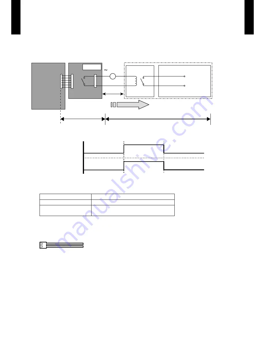
OPERATION STATUS OUTPUT
An air conditioner operation status signal can be output.
Circuit diagram example
z
* Make the distance from the PC board to the connected unit within 10m.
Relay spec. : Max.24VDC, 10mA to less than 500mA.
Field supply
Optional parts
Ex.)Display
Indoor
control PC board Communication kit
Connected unit
Ex.)Relay unit
1
2
Signal
Relay
power
supply
V
Connector
*10 m
24V DC
ON
OFF
Operation
Stop
Indoor unit
Output signal
Parts (Optional)
z
Parts name
Model name
External connect kit
UTY-XWZX
Communication box kit
UTY-XCBXE (for AS
G07/09/12LE)
UTY-XCBXZ1 (for AS
G14LE)
* For operating the EXTERNAL function, the wall mounted type requires the communication kit in addition to the wire
(UTY-XWZX).
Wire (External output) : UTY-XWZX
Содержание AO*G07LEC
Страница 2: ...1 INDOOR UNIT WALL MOUNTED TYPE AS G07LECA AS G09LECA AS G12LECA AS G14LECA DTR_AS049E_03 2011 03 23 ...
Страница 22: ... 01 19 WALL MOUNTED TYPE AS G07 14LE WALL MOUNTED TYPE AS G07 14LE SOUND LEVEL CHECK POINT 88888 ...
Страница 33: ...2 OUTDOOR UNIT SINGLE TYPE AO G07LEC AO G09LEC AO G12LEC AO G14LEC DTR_AO072E_02 2011 03 03 ...
Страница 39: ... 02 05 OUTDOOR UNIT AO G07 14LE OUTDOOR UNIT AO G07 14LE WIRING DIAGRAMS 444 MODEL AO G07LE AO G09LE ...
Страница 40: ... 02 06 OUTDOOR UNIT AO G07 14LE OUTDOOR UNIT AO G07 14LE MODEL AO G12LE AO G14LE ...
Страница 49: ... 02 15 OUTDOOR UNIT AO G07 14LE OUTDOOR UNIT AO G07 14LE SOUND LEVEL CHECK POINT 88888 ...