background image

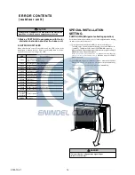
 DANGER

This part (Choke coil) generates high voltages.
Never touch this part.

SPECIAL INSTALLATION
SETTING

PUMP DOWN (Refrigerant collecting operation)

Perform the following procedures to collect the refrigerant when moving
the indoor unit or the outdoor unit.

(1) Press the push-button switch (SW2) on the circuit board once.

The LED on the circuit board starts flashing (one second ON/one se-
cond OFF). This indicates the start of PUMP DOWN operation.
When the switch is pressed while the compressor is in operation, PUMP
DOWN operation starts automatically.
When the switch is pressed while the compressor is in stop, the com-
pressor starts to operate automatically, and then move on to PUMP
DOWN operation.

(2) PUMP DOWN operation continues for about 1 minute. When PUMP

DOWN operation is completed, the compressor stops automatically.
Then close the 2-way valve and 3-way valve immediately.

(3) Turn the power off.

ERROR CONTENTS

(outdoor unit)

1. Make a TEST RUN in accordance with the in-
   stallation instruction sheet for the indoor unit.

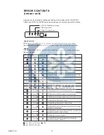
2. OUTDOOR UNIT LEDS

When a malfunction occurs in the outdoor unit, the LED on the circuit
board lights to indicate the error. Refer to the following table for the de-
scription of each error according to the LED.

Error contents

Communication error
(Indoor unit - Outdoor unit)

Discharg pipe temperature sensor

Outdoor heat exchanger temperature sensor

Outdoor temperature sensor

Compressor temperature sensor

Heat sink temperature sensor

Pressure switch abnormal

IPM error

Compressor rotor position cannot detect

Compressor cannot operate

Outdoor fan abnormal (upper fan)

Outdoor fan abnormal (lower fan)

Protect operation

No error

LED

1 flash

2 flash

3 flash

4 flash

7 flash

8 flash

9 flash

12 flash

13 flash

14 flash

15 flash

16 flash

5 sec. ON/

1 sec. OFF

repeated

lighting

 CAUTION

Always turn on the power 12 hours prior to the start of the
operation in order to ensure compressor protection

PUMP DOWN SW (SW2)

2005.10.27

12

www.enindel.com

Содержание ABY45LBAG

Страница 1: ...FICATIONS 1 DIMENSIONS 2 REFRIGERANT SYSTEM DIAGRAM 4 CIRCUIT DIAGRAM 5 ERROR DISPLAY 7 INDOOR PCB CIRCUIT DIAGRAM 8 OUTDOOR PCB CIRCUIT DIAGRAM 11 DISASSEMBLY ILLUSTRATION 13 PARTS LIST 22 ACCESSORIES 24 Indoor unit Outdoor unit ABY45LBAG AOY45LJBYL www enindel com ...

Страница 2: ...G 4 25 E E R COOLING 2 81 HEATING 3 29 STARTING CURRENT A 15 MOISTURE REMOVAL 4 0 FAN MOTOR TYPE Hermetic type 6 poles Induction motor Scroll DISCRIMINATION ANB33FCMMT PRECHARGED REFRIGERANT REFRIGERANT TYPE R410A 3 400 g HIGH FAN SPEED INDOOR MED r p m LOW OUTDOOR INDOOER m h 3 AIR FLOW OURDOOR 1 200 1 100 950 Up Fan 850 Down Fan750 2 000 6 600 ELECTRICAL DATA COMPRESSOR AND REFRIGERANT hr MAX PI...

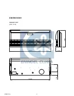
Страница 3: ...DIMENSIONS 1 660 240 700 1 600 130 300 Unit mm INDOOR UNIT 2005 10 26 2 www enindel com ...

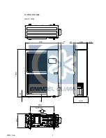
Страница 4: ... Unit mm OUTDOOR UNIT 31 77 900 330 12 9 21 1290 400 650 370 Air Flow 2005 10 26 3 www enindel com ...

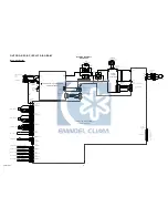
Страница 5: ...Pipe 15 88mm 5 8 Cool Heat Evaporator Refrigerant Pipe 9 52mm 3 8 Charging Valve Charging Valve Accumulator Strainer Compressor Expansion Valve Strainer Condenser Strainer 4 way Valve Muffler x 2 Pressure Check Valve High Pressure Switch 2006 01 23 4 www enindel com ...

Страница 6: ... 6 7 8 1 2 3 4 5 6 7 8 1 2 3 4 5 6 7 8 1 2 3 5 1 1 2 2 3 3 4 4 5 5 1 red red red red black white white red black black black gray gray black brown brown brown orange orange orange yellow yellow yellow CN5 CN16 CN13 CN15 CN10 CN4 CN11 CN8 Step motor left right Fan motor Terminal Use T 3 15A 250V Fuse on F101 Control board Display board Filter board Step motor up down Fan motor capacitor 2005 10 27 ...

Страница 7: ...ge yellow yellow yellow brown brown brown red red red red red red brown red blue black black black black black black white white white white black white black green Fuse 10A white orange Printed circuit board main Printed circuit board filter High pressure SW Solenoid coil 4WV FM FM EV Fan motor 1 Fan motor 2 Expansion valve coil Posistor Earth Earth Earth EMI filter 1T EMI filter 2T EMI filter 3T...

Страница 8: ... 10 27 7 INDOOR PCB CIRCUIT DIAGRAM CONTROLLER PCB ASSEMBLY MAIN PCB K01AL 050HHSE C1 I C 1 uPD780058BGC 108 8BT POWER SOURCE 230V 50Hz POWER SUPPLY PCB EZ 002THSE P INDICATOR PCB EZ 097JHSE D OUTDOOR UNIT www enindel com ...

Страница 9: ... 1TURN UL1015 AWG16 GREEN B W200 SERIAL A CN800 B7B XASK 1 A WHITE CN801 B7B XAKK 1 A BLACK CN27 B6B XARK 1 A RED CN30 179844 1 WHITE CN37 B2B XARK 1 A RED CN36 B2B XASK 1 A WHITE CN26 B2B XAMK 1 A GREEN CN25 B2B XAKK 1 A BLACK CN21 B2B XH AM YELLOW CN22 B2B XH AM RED CN23 B2B XAEK 1 A BLUE 2 1 2 1 2 1 2 1 2 1 2 1 2 1 3 1 6 5 4 3 2 1 2 3 4 5 6 7 1 7 6 5 4 3 2 1 YELLOW BROWN WHITE BLACK RED RED BLA...

Страница 10: ...x 2 C4 PJ 470 25V C5 PJ 220 16V C6 PJ 100 16V C418 PJ 10 35V A R3 100 1W C2 0 047 ECQB R2 1 0K RS 3W C1 220P BN 100K 2W x 2 R6 R1 Q1 2SC4236 R140 1 2 2W D1 D1FL20U 3 2 1 D10 RD5 6ES B2 D2 D1FL20U C3 PJ 100 16V R4 330 1 4W P S I P S I1 P POWER R50 10K 1 10W 5V 1 2 0 022 F x 2 C180 C53 JM156 Q51 2SC2412K BQ 3 R56 27K 1 10W R55 1 0K 1 10W R51 4 7K 1 10W R52 1 0K 1 10W C51 0 022 F 18 14 10 5 4 3 2 1 1...

Страница 11: ...0 1 0K 1 10W 1 SA100 RA 302M C106 3 3 LE C104 0 033 YE C105 0 033 YE C101 3 3 LE VA101 470V TNR VA102 470V TNR B B B B B B B BLACK WHITE TO INDOOR UNIT POWER SOURCE 230V 50Hz EARTH AC VOLT OUT W5 W6 BLACK WHITE W7 GREEN W3 W8 BLACK WHITE W9 W4 L1 RCH4730 021PF07 CN1 B3B XASK 1 A WHITE CT OUT 1 2 3 POWER SUPPLY PCB ASSEMBLY K04BA 0400HUE P0 2005 06 24 10 Model AOY45LJBYL www enindel com ...

Страница 12: ...ited Outdoor high pressure abnormal Outdoor discharge pipe temperature or compressor temperature sensor abnormal OPERATION lamp RED 2 times 2 times 3 times 3 times 4 times 5 times 5 times 6 times TIMER lamp GREEN 2 times 3 times 3 times 4 times 4 times 5 times 5 times 6 times 7 times SWING lamp ORANGE 0 1s ON 0 1s OFF flash OFF 0 5s ON 0 5s OFF flash Error contents Operation can be checked by ligh...

Страница 13: ... 3 Turn the power off ERROR CONTENTS outdoor unit 1 Make a TEST RUN in accordance with the in stallation instruction sheet for the indoor unit 2 OUTDOOR UNIT LEDS When a malfunction occurs in the outdoor unit the LED on the circuit board lights to indicate the error Refer to the following table for the de scription of each error according to the LED Error contents Communication error Indoor unit O...

Страница 14: ...4 386 138 752 735 329 321 69 684 435 434 228 229 580 506 407 505 408 361 396 160 63 868 743 240 146 383 762 74 448 472 223 755 56 388 164 403 181 761 174 387 12 382 379 109 126 122 286 384 Model ABY45LBAG 2005 10 27 13 DISASSEMBLY ILLUSTRATION www enindel com ...

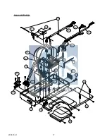
Страница 15: ...Model ABY45LBAG 2005 10 27 14 506 407 505 408 435 434 876 1 69 www enindel com ...

Страница 16: ...Model ABY45LBAG 2005 10 27 15 387 160 91 91 91 321 361 386 www enindel com ...

Страница 17: ...Model ABY45LBAG 2005 10 27 16 876 2 438 684 424 436 387 321 385 868 763 227 63 www enindel com ...

Страница 18: ...Model ABY45LBAG 2005 10 27 17 253 3 34 195 253 4 253 5 253 6 253 7 236 234 380 185 1 625 187 472 448 186 223 381 4 253 2 253 1 875 982 1 815 1 982 2 www enindel com ...

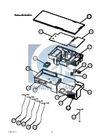
Страница 19: ...1 6 7 5 2 3 4 3 Model AOY45LJBYL 2005 10 27 18 www enindel com ...

Страница 20: ...16 13 12 11 10 9 15 8 14 49 Model AOY45LJBYL 2005 10 27 19 www enindel com ...

Страница 21: ...22 20 21 23 24 19 17 18 26 42 25 Model AOY45LJBYL 2005 10 27 20 www enindel com ...

Страница 22: ...31 38 27 34 35 36 28 39 40 41 30 32 29 33 37 47 46 45 44 43 48 Model AOY45LJBYL 2005 10 27 21 www enindel com ...

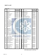
Страница 23: ... 329 Coupling Pipe Assy 9373038214 338 1 Motor Fixture 9359702009 338 2 Motor Fixture B 9359703006 345 1 Filter Guide R 9359692003 345 2 Filter Guide L 9359693000 361 Bushing 9359733003 379 Hinge Plate Grille 9359694007 380 Locking Spacer KGLS 6S 313209391403 381 4 Locking Spacer KGPS 6S 0600118075 382 Cover Decoration R 9359744009 383 Cover Decoration L 9359745006 384 Shaft 9359707004 385 Indicat...

Страница 24: ...B Assy 39 Clamp Cord 40 Terminal 41 Fuse 42 Expansion Valve 43 Thermistor Dischage 44 46 47 48 49 Thermistor Heat Exchanger 45 Thermistor Outdoor 9900156039 Heat Sink Thermistor Wire Pressure Switch 9374607013 9367595051 Coil Choke 9705877016 31 Inverter Box Cover 32 Heat Sink A 33 Act Module 9374417025 9374094028 9374330010 9374173013 9374415014 9374416042 9374174010 9374418046 9366378020 9601882...

Страница 25: ...nt large pipe 2 1 Coupler heat insulator large For indoor side pipe joint small pipe 4 Coupler heat insulator small For fixing the coupler heat insulator Large 4 Small 4 Nylon fastener For installing indoor unit For positioning the indoor unit 4 For installing indoor unit 1 312300787605 0600185534 9305642014 0700019098 9360464002 313806350303 9350716029 9374714025 9352766015 9301501001 31300544665...

Страница 26: ...0510G2926 www enindel com ...

Отзывы: