background image

4

2.3 IDC10 Interface Description

2.4 BGM Adapter USB Configuration

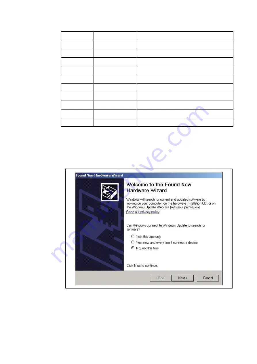
The BGMA is provided with a USB cable. Connect the BGMA to a PC with a USB cable. If the con-
nection is right, the following window will pop up. Follow the instructions displayed, and then click 
“Next”,

Figure 3 Install BGMA in Windows (1)

Pin 

N

umber

Pin 

N

ame

Description

1

UVCC

Target MCU Vcc

2

GND

Target MCU Vss

3

RSTIN

Target MCU reset input

4

RSTOUT

Target MCU reset output

5

RSV

Reserved

6

POUT3V

Supply 3V power out, when this function enabled

7

RSV

Reserved

8

DBG

Target MCU debug pin

9

RSV

Reserved

10

RSV

Reserved

Содержание 8FX MB2146-510-01-E

Страница 1: ...FUJITSU SEMICONDUCTOR SUPPORT SYSTEM SS702 00002 1v0 E New 8FX Family 8 bit MICROCONTROLLER MB95560H 570H 580H Series STARTER KIT MB2146 510 01 E SETUP GUIDE ...

Страница 2: ...BGMA 3 Referred below as the EV Board 4 F2 MC is the abbreviation of FUJITSU Flexible Microcontroller 5 Referred below as the SOFTUNE SOFTUNE is a trademark of Fujitsu Semiconductor Limited Japan Handling and use Handling and use of this product and notes regarding its safe use are described in the manuals for products bundled with the Starter Kit Follow the instructions in the manuals to use this...

Страница 3: ...y from direct sunlight high temperature and high humidity to prevent condensation Do not use or store the product where it is exposed to much dust or a strong magnetic or elec tric field for an extended period of time Inappropriate operating or storage environments may cause a fault Damage Use the product within the ranges given in the specifications Operation over the specified ranges may cause a...

Страница 4: ...tion contained herein The products described in this document are designed developed and manufactured as contemplated for general use including without limitation ordinary industrial use general office use personal use and household use but are not designed developed and manufactured as contemplated 1 for use accompanying fatal risks or dangers that unless extremely high safety is secured could ha...

Страница 5: ...ard 1 USB cable 1 CD ROM SOFTUNE user manuals sample code 1 Hardcopy China RoHS report quick start guide 1 1 2 System Block To setup a debugging system connect a PC a BGMA and an EV board together as shown below Figure 1 BGMA overview 1 3 Handling Precautions The Starter Kit can be used in connection with its bundled products To ensure correct use of this product in a proper environment observe th...

Страница 6: ...ach device relation for the operation voltage and frequency of MCU of operation Compact development environment a light and small BGM Adaptor Since a monitor program is performed in exclusive memory space it does not consume user memory space Continuation execution step execution and break correspondence It connects with a host computer by the USB interface 1 5 Hardware Setup In the hardware setup...

Страница 7: ...s used Function description Remarks Support MB95560 Series MCU MCU MAX machine clock 16 25 MHz MCU power voltage 2 4V 2 to 5 5V 1 Break pointer 256 software breakpoints 3 hardware breakpoints USB interface to PC SOFTUNE Compatible to USB protocol version 2 0 1 Line UART interface to the MB95560 Series MCU The Baud rate is 62 500 bps and can be up to 500kbps set in SOFTUNE Support the MCU flash pro...

Страница 8: ... window will pop up Follow the instructions displayed and then click Next Figure 3 Install BGMA in Windows 1 Pin Number Pin Name Description 1 UVCC Target MCU Vcc 2 GND Target MCU Vss 3 RSTIN Target MCU reset input 4 RSTOUT Target MCU reset output 5 RSV Reserved 6 POUT3V Supply 3V power out when this function enabled 7 RSV Reserved 8 DBG Target MCU debug pin 9 RSV Reserved 10 RSV Reserved ...

Страница 9: ...ect Install from a list or specific location Advanced then click Next Figure 4 Install BGMA in Windows 2 Select Drivers from the folder where SOFTUNE is installed click Next Figure5 Install BGMA in Windows 3 ...

Страница 10: ... Figure 6 Install BGMA in Windows 4 Windows will install the driver automatically Click Finish after the driver has completed the installation normally Then users can find the BGMA is recognized as MB2146 07 in Windows system Figure 7 BGMA is installed in Windows ...

Страница 11: ...urns Green Refer to Figure 8 Figure 8 BGMA Power LED 1 Second plug IDC10 cable to the EV board target MCU board then turn on EV board After that check Power LED on the BGMA turns Orange Refer to Figure 9 Figure 9 BGMA Power LED 2 Green USB Plugged to PC Orange 5V Power Supplied IDC Cable ...

Страница 12: ...lose look of EV board Figure 10 EV board Overview Debug Interface to BGMA Buzzer circuit Potentiometerto MCU AD pin MB95560H 570H 580H MCU LEDs to MCU I O port pins Switch circuit to MCU External Interrupt pins Circuit for LIN UARTPeripheral Communication Power supply either from batteries below the PCB or from 2 pin header Jumpers left open when debug Jumpers to set MCU pins connected to external...

Страница 13: ...k USB 5V power IF external 5V power IF and the battery Reset circuit and reset key Provide IDC10 debug interface LEDs for general use LED1 indicates DBG pin work status Provide one buzzer to demonstrate timer output 2 keys for general use Potentiometer and temperature sensor RS 232 level converter and DB9 interface MAX232 LIN circuit reserved SIO 4 pins reserved All MCU ports are easy accessible t...

Страница 14: ...0 PF0 1 F1 2 VSS 3 VCC 6 Cpin 7 X1A P G2G2 4 X0A P G1 5 TO11 P63 10 P64 EC1 11 TO10 P62 9 P00 AN00 12 P01 AN01 13 P02 I 14 P03 INT03 AN03 SOT 15 P04 INT04 AN04 SI N HCL K1 EC0 16 P05 INT05 AN05 TO00 HCL K2 17 P06 INT06 TO01 18 P07 INT07 19 P12 ECO DBG 20 IC1 MB95560 SOP VI N 1 GND 2 VOUT 3 IC4 C12 BT1 2 3 1 J 1 2 3 CN6 C 5V J3 TP1 TP2 10K 0 1uF 25V 22pF 25V 1 2 3 4 5 6 7 8 9 10 CN3 TEST PIN 1 2 3 ...

Страница 15: ...MCU Vcc and cathode to TP2 MCU GND USB cable The Mini B USB receptacle is only for supplying power to EV board by PC USB port The current and power of this method is limited in 100mA 0 5W Please make sure to supply stable power via the Mini B USB receptacle while operation If any of the power supplies is connected to the EV board correctly power LED LED5 on the EV board will be on Refer to Figure ...

Страница 16: ...is package For the package information please refer to 1 1 Objective and Deliverable 3 4 3 Clock Settings The MB95560H 570H 580H series MCU uses an internal main CR as a clock source by default Us ers can select on board crystal as a main clock and a sub clock Follow the settings below Table 3 SW3 Setting 3 4 4 Buzzer Module A buzzer module is provided to demonstrate an 8 16 composite timer output...

Страница 17: ... I O function Enable LED2 LED3 and LED4 in the following table Table 6 SW2 LED Setting LED module has four LEDs in total but P12 LED1 is not active in a debug mode using BGMA MCU Mode Header name Settings A D VR1 SW2 VR1 A D VR3 SW2 VR3 Modules Header name Settings LED LED2 LED3 LED4 SW2 LED2 LED3 SW1 LED4 SW2 LED3 VR3 VR1 ADC LIN UART KEY SCK SOT SIN LED2 S2 S1 SW2 LED3 VR3 VR1 ADC LIN UART KEY S...

Страница 18: ...ansceiver and a standard DB9 interface with PC Lin module enables an easy setup of Master Slave communication by a Lin bus Table 8 UART Setting LIN module is optional contact your local distributor for the EV board with a LIN module Modules Header name Settings Key S1 S2 SW2 S1 S2 Modules Header name Settings UART SW2 SOT SIN J5 UART J6 UART LIN SW2 SCK SOT SIN J5 LIN J6 LIN SW2 LED3 VR3 VR1 ADC L...

Страница 19: ...asynchronous mode 9 600bps 1 stop bit no parity After a reset the MCU will send Welcome to the LIN UART asynchronous mode of MB95560series 8FX to RS232 transceiver Then the MCU feedbacks any bytes it received SIO project This example uses two EV boards to demonstrate the SIO synchronous mode function 9600bps One MCU keeps sending data while the other keeps receiving One LED is toggled to indicate ...

Страница 20: ...following structure in each project Here take IO_LED project for example shown in Figure 14 Figure 14 I O_LED Project Structure 4 3 Source Code File Description Six files are available in each sample code source code folder shown below Figure 15 Source Code Files ...

Страница 21: ...1 __BYTE P02 1 __BYTE P03 1 __BYTE P04 1 __BYTE P05 1 __BYTE P06 1 __BYTE P07 1 bit struct __BYTE P00 1 __BYTE P01 1 __BYTE P02 1 __BYTE P03 1 __BYTE P04 1 __BYTE P05 1 __BYTE P06 1 __BYTE P07 1 bitc PDR0STR __IO_EXTERN PDR0STR IO_PDR0 define _pdr0 IO_PDR0 define PDR0 IO_PDR0 byte define PDR0_P00 IO_PDR0 bit P00 define PDR0_P01 IO_PDR0 bit P01 define PDR0_P02 IO_PDR0 bit P02 define PDR0_P03 IO_PDR...

Страница 22: ...ange the following code ILR0 0xFF IRQ0 external interrupt ch 0 ch 4 IRQ1 external interrupt ch 1 ch 5 IRQ2 external interrupt ch 2 ch 6 IRQ3 external interrupt ch 3 ch 7 To ILR0 0xFC IRQ0 external interrupt ch 0 ch 4 IRQ1 external interrupt ch 1 ch 5 IRQ2 external interrupt ch 2 ch 6 IRQ3 external interrupt ch 3 ch 7 And declare the interrupt function as in Vectors c below __interrupt void externa...

Страница 23: ...ED project for example Start the SOFTUNE from Startup Menu Programs SOFTUNE V3 FFMC 8L Family SOFTUNE Workbench in Windows Click Open workspace from File Menu in SOFTUNE Select IO_LED wsp in Open Space window Click Start debug from Debug Menu If the entire procedure goes right a debug will start normally 5 3 Operation Precautions All pins of MB95560H 570H 580H MCU are connected to Testing Pin on t...

Страница 24: ...ONDUCTOR SUPPORT SYSYEM New 8FX Family 8 bit MICROCONTROLLER MB95560H 570H 580H Series STARTER KIT MB2146 510 01 E SETUP GUIDE November 2011 the first edition Published FUJITSU SEMICONDUCTOR LIMITED Edited Sales Promotion Department ...

Страница 25: ......

Отзывы: