background image

Property and data protection

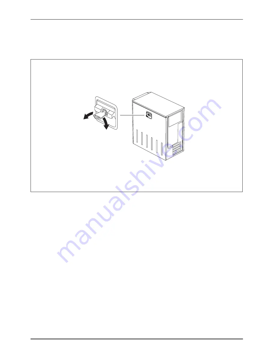
Mechanical casing lock (optional)

Casing mechanicallock

Casing

Lock

Casing lock

With the casing lock you can mechanically lock the casing to prohibit unauthorised persons
from opening it. The keys can be found on the rear panel of your device.

2

1

Locking the casing

Turn the key in the direction of the arrow (1).

Unlocking the casing

Turn the key in the direction of the arrow (2).

26

A26361-K1182-Z120-1-7619, edition 3

Содержание Primergy Econel 100 Series

Страница 1: ...Server English Operating Manual PRIMERGY Econel 100 130 Series ...

Страница 2: ...elp Desk refer to the enclosed Help Desk List or go to http www fujitsu siemens com support your sales partner your sales office Further information can be found in the Safety and Warranty manuals Latest information about our products useful tips updates etc are available on our website www fujitsu siemens com ...

Страница 3: ......

Страница 4: ...This manual was produced by Xerox Global Services Published by Fujitsu Siemens Computers GmbH AG 02 08 Edition 3 Order no A26361 K1182 Z120 1 7619 ...

Страница 5: ...100 130 Series Your PRIMERGY Econel Server 1 Important notes 4 Getting started 8 Operation 19 Property and data protection 25 Troubleshooting and tips 30 System expansions 35 Technical data 61 Index 62 Operating Manual ...

Страница 6: ... 2008 All rights reserved including rights of translation reproduction by printing copying or similar methods in part or in whole In the event of violations perpetrators will be liable to prosecution for damages All rights reserved including rights created by patent grant or registration of a utility model or design Subject to availability and technical modifications ...

Страница 7: ...vices to the parallel or serial port 13 Connecting external devices to the USB ports 14 Connecting the device to the mains voltage device dependent 15 Switching on monitor and device 16 Switching on the device with main power switch 17 Switching on the device without main power switch 18 Installing the software 18 Operation 19 Switch the device on 19 Switching off the device 19 Other ways of switc...

Страница 8: ...over 40 Installing the locking device with casing lock 41 Removing the locking device 41 Installing the locking device with casing lock 42 Removing ventilation duct 43 Ventilation duct installing 44 Installing and removing heat sinks 45 Removing heat sinks 45 Installing heat sinks 46 Installing and removing additional fans devices with four hard disks 46 Removing additional fans 47 Installing addi...

Страница 9: ...Contents Index 62 A26361 K1182 Z120 1 7619 edition 3 ...

Страница 10: ...Contents A26361 K1182 Z120 1 7619 edition 3 ...

Страница 11: ...Siemens Computers utilities supports fast BIOS update Security functions in the BIOS Setup and on the mainboard protect the data on the server against manipulation Due to the supported RAID level the hard drive controllers offer error tolerance through data redundancy for users requiring complete protection for their valuable data This manual tells you how to start using your device and how to ope...

Страница 12: ... password Name123 or a command to launch a program start exe This style refers to information displayed by a program on the screen e g Installation is completed This style is for terms and texts in a software user interface e g Click Save names of programs or files e g Windows or setup exe This style is for cross references to another section e g Safety information cross references to an external ...

Страница 13: ...rs Utilities DVD supplied with every device as part of the ServerView Suite software Type of information Where Getting Started Hardware poster Printed Information on ServerView Suite software ServerStart DVD ServerBooks DVD ServerSupport DVDs BIOS Setup manual PDF file RAID software manual PDF file Safety manual Printed Warranty manual PDF file Ergonomics manual PDF file Returning used devices man...

Страница 14: ...ins voltage remove the power plug from the power socket Replace the lithium battery on the mainboard in accordance with the instructions in the manual for the mainboard Use only notebooks with protection class 2 The activities described in these instructions must only be performed by qualified engineers Repairs to the device must only be performed by qualified technicians Unauthorised opening and ...

Страница 15: ...ipes to clean the keyboard and the mouse Air filters should be cleaned or replaced on a regular basis Clogged or soiled air filters will result in increased interior temperatures in the device Excessively high operating temperatures may result in loss of data and or unreliable operation Energy saving disposal and recycling Disposal Energysaving Recycling Drivers UtilitiesDVD UserDocumentationDVD F...

Страница 16: ...on reception which can be determined by turning the equipment off and on the user is encouraged to try to correct the interference by one or more of the following measures Reorient or relocate the receiving antenna Increase the separation between equipment and the receiver Connect the equipment into an outlet on a circuit different from that to which the receiver is connected Consult the dealer or...

Страница 17: ...nt does cause harmful interference to radio or television reception which can be determined by turning the equipment off and on the user is encouraged to try to correct the interference by one or more of the following measures Reorient or relocate the receiving antenna Increase the separation between equipment and the receiver Connect the equipment into an outlet on a circuit different from that t...

Страница 18: ... not correspond to the delivery note or if any part of the delivery is damaged please notify your local sales outlet immediately refer to Troubleshooting and tips Page 30 for more information Steps for initial setup Preparingforfirstuse overview Preparingforuse Only a few steps are necessary to put your new device into operation for the first time Select a location for device and set up device Con...

Страница 19: ...s and noises may occur To prevent this a distance of at least 3 mm should be maintained from other devices on casing sides without ventilation surfaces In addition we recommend placing the device on support feet as these buffer vibrations Make sure that the device is adequately ventilated In order to avoid overheating do not cover the ventilation area of the monitor or the device Do not expose the...

Страница 20: ...he external devices Please make sure that you always observe the safety notes provided in Important notes Page 4 Plug all data communication cables into the appropriate sockets Plug all power cables into the grounded mains outlets USB devices are hot pluggable This means you can connect and disconnect USB cables while your device is switched on Additional information can be found in Connecting ext...

Страница 21: ...rface Printer 1 Serial port 1 turquoise Serialport 2 Serial port 2 turquoise Serialport Monitor port blue Monitorport Microphone jack mono pink Microphoneport Headphones port orange or light green Наушники Audio input Line in light blue Audioinput Linein Audio output Line out light green Audiooutput Lineout SCSI connection SCSIconnection SCSI USB Universal Serial Bus black UniversalSerialBus LAN L...

Страница 22: ...r cable may only be connected to the device monitor socket if the monitor current consumption is less than 1 5 A for 230 V or 3 A for 115 V The values for the monitor current consumption can be found in the technical data on the monitor or in the operating manual for the monitor 1 2 Depending on your device configuration level plug the monitor power cable into either the system unit 1 or a grounde...

Страница 23: ...angular USB plug of the keyboard cable into one of the device s USB ports USBport Connecting a PS 2 keyboard Use the supplied keyboard cable only ConnectingaPS 2keyboard Connecting Plug the rectangular connector of the keyboard cable into the rectangular socket on the underside or on the rear of the keyboard Plug the round plug of the keyboard cable into the keyboard port on the device Keyboard Co...

Страница 24: ...ans you can connect and disconnect USB cables while your device is switched on Additional information can be found in the documentation for the USB devices Connect the data cable to the external device Connect the data cable to one of the USB ports on your device Device drivers The external USB devices you connect to the USB ports usually require no driver of their own as the required software is ...

Страница 25: ...ting 100 V 127 V 200 V 240 V 115 230 1 a a 100 V 127 V 200 V 240 V 230 115 2 230 115 1 Sliding voltage switchover switch 2 Plug in voltage switchover element a Notch for inserting the screwdriver The visible value must correspond to the local mains voltage 115 100 V to 127 V 230 200 V to 240 V Check the voltage setting If the incorrect mains voltage is selected push the slide switch all the way in...

Страница 26: ... on the version the device may be equipped with a main power switch on the back of the device in addition to the ON OFF button on the front As a result there are different ways to switch on the two variants Switch the monitor on see the operating manual for the monitor Switch the device on To do this follow the instructions below 16 A26361 K1182 Z120 1 7619 edition 3 ...

Страница 27: ... 1 2 I 0 Device is off I Device is on Switch the device on with the main power switch 1 on the back of the device Press the ON OFF switch 2 on the front of the device The power on indicator lights green and the device is started A26361 K1182 Z120 1 7619 edition 3 17 ...

Страница 28: ...3 Installation with ServerStart Switch the device on Place the ServerStart CD or an installation disk in the corresponding drive Follow the instructions on the screen see Configuring with ServerStart or EasySetup Page 23 or Configuration without ServerStart Page 23 For instructions on how to operate ServerStart and further information refer to the ServerView Suite ServerStart manual supplied as a ...

Страница 29: ...he Start menu and the Turn Off Computer function Device Monitor If the operating system does not automatically switch the device into energy saving mode or switch it off press the ON OFF switch If the device is in standby it consumes a minimum of energy Switch the device off at the main switch if present The device no longer uses any power The main switch and the ON OFF switch do not disconnect th...

Страница 30: ...ia the LAN After power failure A switched on device is automatically restarted after a power failure depending on the BIOS setting Power override function The device can be turned off by pressing the On Off switch firmly for a long period 4 5 seconds Data may be lost when using the power override function Indicators on the device Indicators Device The indicators are on the front of the casing Whic...

Страница 31: ...ving mode Indicator does not light up Device is switched off and disconnected from the power supply Floppy disk indicator Floppydiskdrive The indicator lights up when the floppy disk drive of the device is accessed You may only remove the floppy disk when the indicator is unlit Drive indicator e g DVD DVDindicator DVDindicator CD ROMindicator CD ROMdrive The indicator lights up when the CD ROM or ...

Страница 32: ... Advanced Configuration and Power Management Interface Otherwise the key is inoperative The mainboard must support this function Keys Keys Keys Enter key confirms the highlighted selection The Enter key is also referred to as the Return key Start key Keys calls up the Windows Start menu Keys Menu key calls up the menu for the marked item Windows Keys Keys Shift key enables upper case letters and t...

Страница 33: ...ons makes it easy for you to configure the device and then install the operating system The menu driven configuration process includes server configuration with SCU and RAID controller configuration Information about using ServerStart can be found in the PRIMERGY ServerView Suite ServerStart manual on the ServerStart CD Further information about using EasySetup is provided on the Drivers Utilities...

Страница 34: ...upplied software is recommended The controller has its own configuration utility Further information can be found in the RAID software manual on the Drivers Utilities DVD Settings in BIOS Setup BIOSSetup Systemsettings BIOSSetup BIOSSetup BIOSSetup Setup In BIOS Setup you can set the system functions and the hardware configuration of the device When the PC is delivered the default entries are vali...

Страница 35: ...uthorised access You can also combine these functions Mechanical access protection Detection of unauthorised opening The server is equipped with a device to detect unauthorised opening of the casing Intrusion Detection Switch With the help of this detector the ServerView program is able to recognise when the cover of the device is removed without authorisation and generates a corresponding alarm m...

Страница 36: ...ng lock you can mechanically lock the casing to prohibit unauthorised persons from opening it The keys can be found on the rear panel of your device 2 1 Locking the casing Turn the key in the direction of the arrow 1 Unlocking the casing Turn the key in the direction of the arrow 2 26 A26361 K1182 Z120 1 7619 edition 3 ...

Страница 37: ...ur device from theft with the holes 1 a padlock and a chain which you have connected to a fixed object beforehand with the Kensington Lock device 2 and a Kensington MicroSaver Consult the manual for your Kensington Lock Lead sealing The casing can be sealed to prevent it being opened by unauthorised persons To do this feed the sealing chain through the holes 1 and seal the chain with the lead seal...

Страница 38: ...drive Issuing virus warnings Preventing the unauthorised writing of floppy disks Protecting BIOS from overwriting Protecting the device from being switched on by an external device You can also combine these functions You will find a detailed description of the Security menus and how to assign passwords in the manual for the mainboard or in the BIOS Setup manual Access authorisation via external S...

Страница 39: ...other security software in addition to SystemLock e g SMARTY please read your security software documentation beforehand SystemLock rights You can initialise a SmartCard with one of the following rights System The system starts following entry of the user PIN You can change the user PIN Setup You can open and change the BIOS Setup and change the user PIN System Setup The system starts following en...

Страница 40: ...note of any error messages displayed Note the ID number of your device The ID number can be found on the type rating plate on the back of the casing Please contact your sales outlet or our service department refer to the enclosed Help Desk List or go to http www fujitsu siemens com support Troubleshooting Power indicator remains off after you have switched on your device Cause Remedy The mains vol...

Страница 41: ...ivate the screen saver If necessary enter the appropriate password Brightness control is set to dark Adjust the brightness control For detailed information please refer to the operating manual supplied with your monitor Power cable not connected Switch off the monitor and the device Check that the monitor power cable is properly connected to the monitor and to a grounded mains outlet or to the mon...

Страница 42: ...OS Setup check the settings in the Advanced menu under Peripheral Configuration Mouse Controller If necessary change the setting to Enabled or Auto Detect The floppy disk cannot be read or written Cause Remedy The write protection of the floppy disk or the floppy disk drive is activated Check whether the write protection of the floppy disk or the floppy disk drive is activated refer to the BIOS Se...

Страница 43: ...ontroller manual see Information sources Page 3 If the drive is still faulty replace it see Installing and removing drives Page 52 Time and or date is not correct Cause Troubleshooting Time and date are wrongly set Set the correct time and date within the operating system you are using or Set the correct time and or date in the BIOS Setup The on board lithium battery in the device is flat If the t...

Страница 44: ...talling programs or drivers important files may be overwritten and modified To be able to access the original data in the event of any problems following installation you should backup your hard disk prior to installation 34 A26361 K1182 Z120 1 7619 edition 3 ...

Страница 45: ... manual for the mainboard When installing components that become very hot make sure that the maximum permissible temperature is not exceeded The device must be switched off when installing removing the system expansions and may not be in energy saving mode Remove the power plug before opening the device This chapter describes all the activities required to modify your device hardware e g installin...

Страница 46: ... e g by touching a grounded object before working The equipment and tools you use must be free of static charges Only touch or hold the boards by the edge or at the areas marked green Touch Points Never touch pins or conductors on boards fitted with ESDs Disconnect the mains plug before inserting or removing components When installing components use a suitable earthing cable to connect them to a b...

Страница 47: ...s Page 4 Unplug the mains plug from the mains outlet Do not insert the power plug until you have closed the casing Remove any plugged in cables that are in the way On devices with a casing lock Unlock the casing Lay the device on its side in the manner shown below 1 2 Pull the locking device 1 and swivel the side part in the direction of the arrow 2 A26361 K1182 Z120 1 7619 edition 3 37 ...

Страница 48: ...ve cage Remove the device cover Cover removal Page 37 2 1 Unscrew the knurled screw 1 Fold open the drive cage 2 Thanks to the integrated torque controller the drive cage will stop in any position 38 A26361 K1182 Z120 1 7619 edition 3 ...

Страница 49: ...ns Closing the casing Closing the drive cage When closing the drive cage take care not to trap any cables 2 1 Close the drive cage 1 Secure the drive cage with the knurled screw 2 A26361 K1182 Z120 1 7619 edition 3 39 ...

Страница 50: ...he guide rail on the lower part of the casing Casing Device Swivel the side part in the direction of the arrow 1 until it engages On devices with a casing lock Lock the casing Reconnect the cables that you disconnected previously 40 A26361 K1182 Z120 1 7619 edition 3 ...

Страница 51: ...the casing see Opening the casing Page 37 Place the removed side part on a flat surface with the inside facing upwards 1 1 2 Press the catch in the direction of the arrow 1 Carefully thread the locking device out of the side part in the direction of the arrow 2 A26361 K1182 Z120 1 7619 edition 3 41 ...

Страница 52: ...so that the outside faces upwards Guide the locking device with the casing lock in the direction of the arrow 1 into the side part Press the catch in the direction of the arrow 2 and at the same time press the locking device into the side part 3 until the catch engages 42 A26361 K1182 Z120 1 7619 edition 3 ...

Страница 53: ...sing see Opening the casing Page 37 Unhook the wires from the holder on the ventilation duct Remove any connected wires which are in the way Unlock the ventilation duct by pressing locking hooks in the direction of the arrow 1 Keep pressing the locking hook and pull the ventilation duct in the direction of the arrow 2 out from the casing A26361 K1182 Z120 1 7619 edition 3 43 ...

Страница 54: ... underside of the ventilation duct into the corresponding slots in the casing Press the ventilation duct into the casing in the direction of the arrow 1 so that the locking hook is felt to engage Reconnect the cables that you disconnected previously Hook the wires into the holder on the ventilation duct Close the casing see Closing the casing Page 39 44 A26361 K1182 Z120 1 7619 edition 3 ...

Страница 55: ... heat sinks Removing heat sinks Remove the ventilation duct see Removing ventilation duct Page 43 Disconnect the cables to the heat sink 1 1 1 1 2 Loosen the screws 1 Lift the heat sink out of the casing 2 A26361 K1182 Z120 1 7619 edition 3 45 ...

Страница 56: ... screw holes on the mainboard Fasten the screws 2 Connect the cables to the heat sink Install the ventilation duct again see Ventilation duct installing Page 44 Installing and removing additional fans devices with four hard disks An additional fan is only included in devices that can be fitted with four hard disk drives 46 A26361 K1182 Z120 1 7619 edition 3 ...

Страница 57: ...irection of the arrow 3 Disconnect the cables to the fan Lift the fan out of the device Installing additional fans 2 1 Connect the cables to the fan Insert the fan into the casing 1 Ensure that the clip on the fan is inserted into the two corresponding slots in the casing Press on the catch and ensure that the fan clicks audibly into the casing 2 A26361 K1182 Z120 1 7619 edition 3 47 ...

Страница 58: ...already be installed on shipment Board Board Remove the slot cover Open the casing see Opening the casing Page 37 1 2 Loosen the screw 1 Pull the slot cover out of the slot 2 Do not throw away the slot cover For cooling protection against fire and in order to comply with EMC regulations you must refit the slot cover if you remove the board 48 A26361 K1182 Z120 1 7619 edition 3 ...

Страница 59: ...ed a board please check the relevant PCI slot settings in the BIOS Setup If necessary change the settings Further information is provided in the PCI board documentation Removing boards If necessary disconnect the cables which are connected to the board 2 1 Loosen the screw 1 Pull the board out of the slot 2 Place the board in suitable packaging A26361 K1182 Z120 1 7619 edition 3 49 ...

Страница 60: ...refit the slot cover 2 1 Push the slot cover into the slot 1 Tighten the screw 2 Close the casing see Closing the casing Page 39 If you have installed or removed a board please check the relevant PCI slot settings in the BIOS Setup If necessary change the settings Further information is provided in the PCI board documentation 50 A26361 K1182 Z120 1 7619 edition 3 ...

Страница 61: ... For cooling protection against fire and in order to comply with EMC regulations you must refit the slot cover if you remove the board EMC electromagneticcompatibility Remove the required slot cover see Installing and removing a board Page 48 Fitting a slot adapter 2 1 Fit the slot adapter to the slot cover of the low profile board 1 and screw tight 2 Low profileboards Now you can install the low ...

Страница 62: ...Depending on the device expansion stage two non accessible drives two 3 inch drives with half installation height or four non accessible drives four 3 inch drives with half installation height Accessible drives are e g DVD or CD ROM drives into which a data medium can be inserted from outside Non accessible drives are e g hard disk drives The number of screws used to attach the drives varies accor...

Страница 63: ... from behind slide the drive a short distance out of the bay in the direction of the arrow 2 The drive now protrudes slightly out of the casing Pull the drive out of the casing 2 If necessary make the required settings on the remaining hard disk drive If you are not installing a new drive close the opening with a cover Close the casing see Closing the casing Page 39 It may be necessary to modify t...

Страница 64: ... of drives already installed as well Master Slave 1 2 Slide the drive into the casing as far as it will go 1 Fasten the drive in place with the screws 2 Plug the data and the power supply connectors into the drive Make sure the polarity is correct In the case of improper use of the cutting tool there is a risk of injury and damage to the casing Beware of sharp edges when cutting out the installati...

Страница 65: ...ive data cable power supply cable 1 2 Remove the screws 1 Working from behind slide the floppy disk drive out of the bay in the direction of the arrow 2 2 1 Slide the new floppy disk drive into the casing as far as it will go 1 Fasten the floppy disk drive with the screws 2 Fit the data and power supply connectors to the floppy disk drive Make sure the polarity is correct A26361 K1182 Z120 1 7619 ...

Страница 66: ...ve the drive again later If you are installing a second drive push the cover 3 out of the casing and remove the installation panel beneath it using a cutting tool Close the casing see Closing the casing Page 39 It may be necessary to modify the entry for the drive in the BIOS Setup Installing and removing the hard disk drive Harddiskdrive Harddiskdrive Harddiskdrive Removing a hard disk drive Open...

Страница 67: ...2 1 Slightly press together the EasyChange rails mounted on the hard disk 1 and pull the hard disk drive out of the drive cage in the direction of the arrow 2 Pull the EasyChange rails off the hard disk drive If necessary make the required settings on the remaining hard disk drive A26361 K1182 Z120 1 7619 edition 3 57 ...

Страница 68: ... 37 Harddiskdrive Take the new hard disk drive out of its packaging Secure the EasyChange rails on the side of the hard disk by inserting the pins of the EasyChange rail in the corresponding holes of the hard disk EasyChange rails for a second hard disk drive are mounted on the drive cage You can install the second hard disk drive in exactly the same way as described in this section 58 A26361 K118...

Страница 69: ...able power supply to the drive and to the fan Close the casing see Closing the casing Page 39 Mainboard expansions Details on how to upgrade the main memory or the processor of your device can be found in the manual for the mainboard Upgrades Lithiumbattery Processor Mainmemory Mainboard Upgrading main memory Open the casing see Opening the casing Page 37 Mainmemory Upgrade the memory according to...

Страница 70: ...ion duct Page 43 Remove the heat sink see Removing heat sinks Page 45 Upgrade the processor according to the description in the manual for the mainboard Fit the heat sink see Installing heat sinks Page 46 Install the ventilation duct see Ventilation duct installing Page 44 Close the casing see Closing the casing Page 39 60 A26361 K1182 Z120 1 7619 edition 3 ...

Страница 71: ... monitor socket output 100 V 127 V 3 0 A 200 V 240 V 1 5 A Dimensions Width x depth x height 203 mm x 387 mm x 390 mm Weight in basic configuration approx 11 kg Environmental conditions Environment class 3K2 DIN IEC 721 part 3 3 Environment class 2K2 DIN IEC 721 part 3 2 Temperature Operating 3K2 15 C 35 C Transportation 2K2 25 C 60 C Condensation must be avoided during operation The data sheet of...

Страница 72: ...tion 23 SATA RAID controller 24 Connecting a PS 2 keyboard 13 Connecting device 15 keyboard 13 mouse 13 PS 2 keyboard 13 PS 2 mouse 13 USB keyboard 13 Contents of delivery 8 Cord see Cable 10 Ctrl Alt Del 23 Cursor keys 21 D Data protection 25 Device Connections 11 Device drivers Parallel port 14 Device drivers Serial port 14 Device anti theft protection 27 checking rated voltage 15 closing 40 con...

Страница 73: ...pad 21 connecting 13 cursor keys 21 function keys 21 numeric keypad 21 port 13 Keys 22 Keys Alt Gr 22 Control 23 Ctrl 23 Ctrl key 23 Ctrl Alt Del 23 cursor keys 21 Enter 22 Enter key 22 menu key 22 Num Lock 22 Return 22 shift 22 shift key 22 Start key 22 L LAN port 11 Lead sealing 27 Line in 11 Line out 11 Lithium battery 59 Lock 26 Low voltage directive 5 Low profile board 51 Low profile boards f...

Страница 74: ...roller Configuration 24 SCSI Port 11 SCSI connection 11 Security functions BIOS Setup 28 SmartCard 28 29 SystemLock 29 Security measures 25 Serial port 11 13 Connecting devices 13 Serial port Settings 13 Setup see BIOS Setup 24 SmartCard reader operating 29 System expansion 35 System settings BIOS Setup 24 System unit see Device 5 T Target group 1 Technical data 61 Transportation 4 5 U Universal S...

Страница 75: ...tsu com Copyright Fujitsu Technology Solutions 2009 Hinweise zum vorliegenden Dokument Zum 1 April 2009 ist Fujitsu Siemens Computers in den alleinigen Besitz von Fujitsu übergegangen Diese neue Tochtergesellschaft von Fujitsu trägt seit dem den Namen Fujitsu Technology Solutions Das vorliegende Dokument aus dem Dokumentenarchiv bezieht sich auf eine bereits vor längerer Zeit freigegebene oder nic...

Отзывы: