59
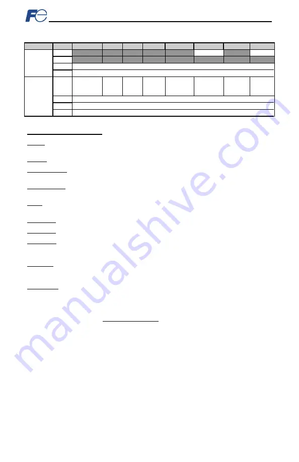
Table 24: Input Instances 70 and 71 Detail
Instance Byte
Bit 7
Bit 6 Bit 5
Bit 4
Bit 3
Bit 2
Bit 1
Bit 0
70
0
Running1
Faulted
1
2
Speed Actual (Low Byte)
3
Speed Actual (High Byte)
71
0
At
Reference
Ref
From
Net
Ctrl
From
Net
Ready Running2
(REV)
Running1
(FWD)
Warning Faulted
1
Drive State
2
Speed Actual (Low Byte)
3
Speed Actual (High Byte)
Input Instance Mapping Detail
Faulted: Inverter fault signal (0=not faulted, 1=faulted). Maps to function code M14, bit 11 (operation
status word, ALM bit).
Warning: This bit is not used (it is always 0).
Running1 (FWD): Running forward status signal (0=not running forward, 1=running forward). Maps to
function code M14, bit 0 (operation status word, FWD bit).
Running2 (REV): Running reverse status signal (0=not running reverse, 1=running reverse). Maps to
function code M14, bit 1 (operation status word, REV bit).
Ready: Inverter ready signal (0=not ready, 1=ready). The Ready bit will be 1 whenever the Drive State
attribute (see below) is in the Ready, Enabled or Stopping state.
CtrlFromNet: This bit is not used (it is always 0).
RefFromNet: This bit is not used (it is always 0).
AtReference: Up-to-speed signal (0=not up-to-speed, 1=up-to-speed). Set to 1 if the inverter is running
(either Running1 = 1 or Running2 = 1) and both the ACC bit (bit #9) and DEC bit (bit #10) in the
operation status word (function code M14) are 0.
Drive State: Indicates the current state of the Control Supervisor Object state machine. Refer to the
ODVA EtherNet/IP specification (object library) for detailed information on the Control Supervisor Object
state machine.
Speed Actual: Inverter operating speed in RPM. Maps to function code M09 (output frequency). The
speed actual component of the AC/DC drive profile input instances is always in units of RPM. Therefore,
the interface card applies the Hz-to-RPM conversion indicated in Equation 6 in order to determine the
appropriate operating speed (in units of RPM) to be written to the network.
poles
motor
of
number
120
x
Hz
RPM
=
Equation 6
The “number of motor poles” term which appears in the denominator of Equation 6 is obtained from the
setting of inverter function code P01 (Motor number of poles). Note that the value of P01 is read by the
interface card only at boot-up, so if the value of this function code is changed, then the interface card
must be rebooted in order for it to read the new value from the inverter.
9.2.7 Explicit Messaging Via Get/Set Attribute Single Services
Get attribute single (0x0E) and set attribute single (0x10) are common services that can access the
inverter function codes by specifying the appropriate class code, instance number and attribute identifier.
The class code is 0xA2. The instance number is the register number that is associated with the targeted
inverter function code (refer to section 4.1). The attribute identifier is 1, which is the 16-bit value of the
function code being accessed.
For example, a get attribute single request with a class code of 0xA2, instance number of 2058, and
attribute identifier of 1 will return the 16-bit value of inverter function code M09 (Output frequency).
Содержание OPC-PRT
Страница 18: ...17 Figure 5 Installation for 15 kW and Smaller Inverters Interface Card Connector Board Option Case...
Страница 19: ...18 Figure 6 Installation for 18 5 kW to 22 kW Inverters Interface Card Connector Board Option Case...
Страница 86: ...85 Figure 85 Monitoring the Data Being Read from the Inverter...
Страница 116: ...47520 Westinghouse Dr Fremont CA 94539 Tel 510 440 1060 Fax 510 440 1063 http www americas fujielectric com...


