

- 1 -
Quick Installation Guide
“OPC-ETH” Multiprotocol Ethernet Interface Card
Thank you for purchasing the OPC-ETH Multiprotocol Ethernet Interface (herein after called the OPC-ETH card). This quick installation
guide has been prepared to help you connect your inverter to Modbus/TCP, EtherNet/IP, Allen Bradley CSP, and BACnet/IP networks.
Of the three option connection ports (A-, B-, and C-ports) provided on the inverter, the OPC-ETH card is mechanically keyed to
allow installation only onto the A-port. Once the inverter is equipped with this card, no other fieldbus cards (e.g., DeviceNet) are
allowed on the inverter. Mounting more than one fieldbus card onto the inverter will result in an
“Er4”
trip, which cannot be
reset until all cards but one are removed. Refer to section "6. Inverter Faults" for more information about the
“Er4
” trip.
1. Unpacking Confirmation
(1) Ensure that the OPC-ETH card and two M3x6
mounting screws are contained in the package.
(2) Ensure that the OPC-ETH card was not damaged
during transport (no broken components, dents or
warpage.)
(3) Ensure that the model name "OPC-ETH" is
printed on the OPC-ETH card (Figure 1).
If you suspect the device is not working properly or if
you have any questions about the device, please
contact the seller or your local Fuji representative.
Figure 1: OPC-ETH Top Side
Figure 2: OPC-ETH Bottom side
2. Installation
Before starting installation and wiring, turn OFF the inverter’s power and wait at least 10 minutes. Additionally, ensure that the charge
lamp is turned OFF and confirm that the DC link bus voltage as measured between the P(+) and N(-) terminals is at a safe level (+25
VDC or less) using a multimeter or similar instrument.
Failure to follow this precaution may result in an electric shock.
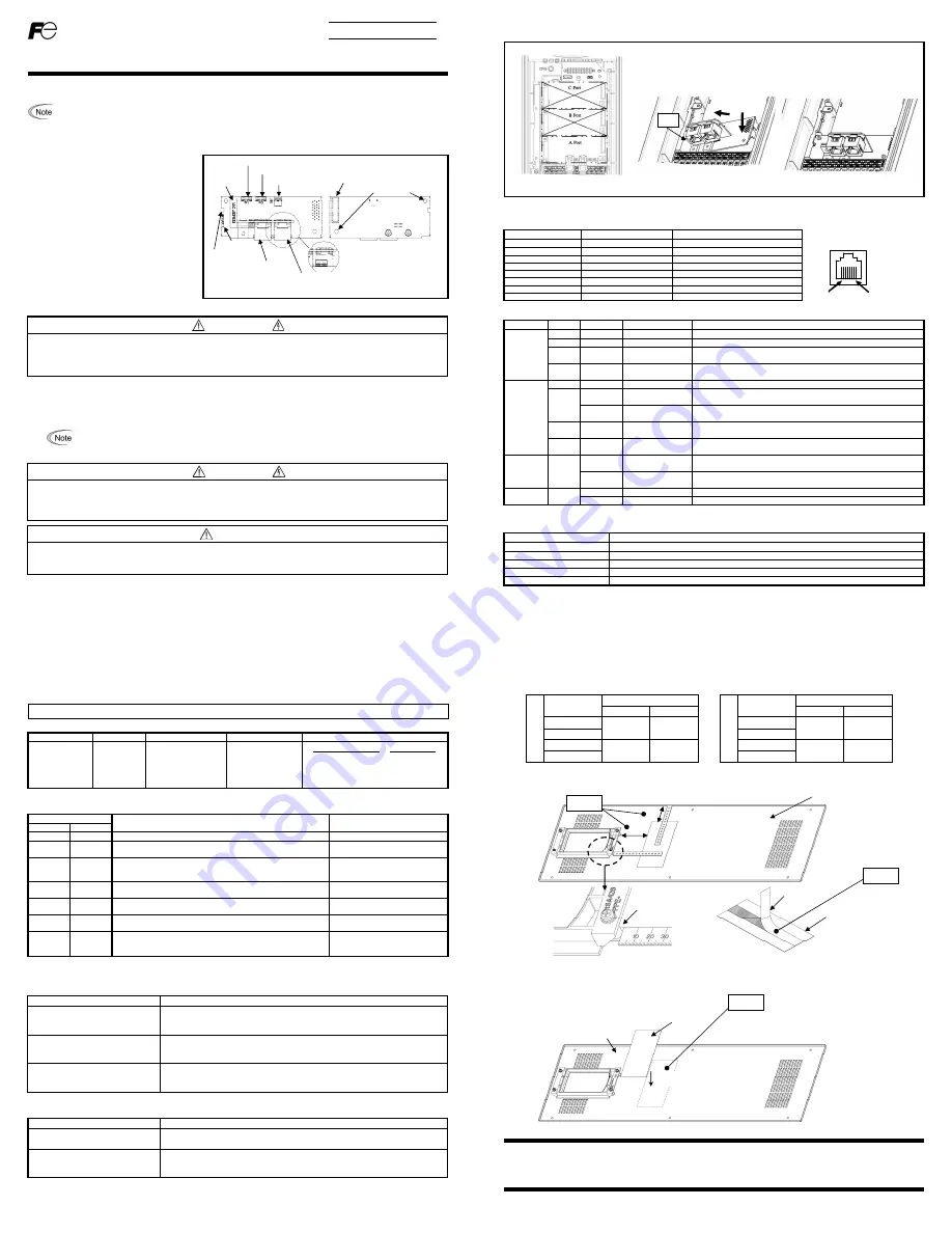
(1) Remove the front cover from the inverter to expose the control printed circuit board (control PCB) (Figure 3).
To remove the front cover, refer to the Inverter Instruction Manual.
(2) Insert connector CN1 located on the back side of the OPC-ETH card (Figure 2) into the A-port (CN4) on the inverter control PCB.
Next, install and tighten the mounting screws that came with the OPC-ETH card (Figure 4).
Confirm that the positioning notch (Figure 1) is fitted on the tab (
in Figure 4) and connector CN1 is
fully inserted (
in Figure 4). Figure 5 shows the OPC-ETH card correctly mounted.
(3) Connect the network cables as necessary. Insert the Ethernet cables into the Ethernet jacks.
In general, the insulation for control signal wires is not specifically designed to withstand high voltages (i.e. reinforced insulation is not
applied). Therefore, if a control signal wire comes into direct contact with a live conductor, the insulation may prematurely fail and
expose the signal wire to high voltages. Ensure that the control signal wires will not come into contact with live conductors.
Failure to follow this precaution may result in an electric shock.
Electrical noise may be emitted from the inverter, motor and wires. Take appropriate measures to prevent nearby sensors and similar
devices from malfunctioning due to ambient electrical noise.
Failure to follow this precaution may result in device malfunction.
Port1 Ethernet jack
Module Status and
Network Status LEDs
(below Ethernet jack)
Port2 Ethernet jack
Positioning
notch
MAC
Address
Standoff mounting holes
CN1 Inverter control board connector
USB port
Port1 Link / Activity and Speed LEDs
Port2 Link / Activity and Speed LEDs
Model
WARNING
WARNING
CAUTION
- 2 -
(4) Reinstall the front cover.
To reinstall the front cover, refer to the Inverter Instruction Manual.
3. Component Overview
3.1 RJ-45 Ethernet Connectors
The interface card has two RJ-45 connectors. The table below lists the pin assignments.
3.2 Status Indicator LEDs
Name
Color
Status
Summary Description
MODULE
STATUS
(MS)
-
OFF
No power
If the device is powered off, the module status LED is off
Green
Solid
Device operational If the device is operating correctly, the module status LED is solid green
Red Flashing
Major
fault
If the device has detected a non-recoverable major fault, the module
status LED will be flashing a red error code
Green /
Red
Flashing
Startup
On startup, the module status LED will flash green / red
NETWORK
STATUS
(NS)
-
OFF
No power
If the device is powered off, the network status LED is off
Green
Solid Connected
If an EtherNet/IP connection is established, the network status LED is
solid green
Flashing No
connections
If the device has no established EtherNet/IP connections, the network
status LED will be flashing green
Red Flashing
Connection
timeout
If one or more EtherNet/IP connections have timed out, the network
status LED will be flashing red
Green /
Red
Flashing
Startup
On startup, the network status LED will flash green / red
LINK/ACT Green
Solid Ethernet
link
The green “LNK/ACT” LEDs (one for each Ethernet port) are lit
whenever a viable Ethernet network is connected
Flashing
Send/Receive
activity
The green “LNK/ACT” LEDs (one for each Ethernet port) blink when
network packets are sent or received on the associated port
SPEED Yellow
Solid
100Mbps
Link speed is 100Mbps
OFF
10Mbps
Link speed is 10Mbps
Note: The “MS” and ”NS” LEDs conform to the behavior as dictated in “THE CIP NETWORKS LIBRARY Volume 2, Chapter 9”.
4. Ethernet Communication Specifications
Item
Description
Ethernet standard
IEEE 802.3 10/100BaseT Ethernet compliant. (autosense/autonegotiation and auto-MDIX)
Cable
CAT5-type 8 UTP
Communication speed
10Mbps or 100Mbps
Connector RJ-45
Transmission distance
Max. 100m
Pin #
Pin Assignment
Description
1 TX+
Transmit
(+)
2 TX-
Transmit
(-)
3 RX+
Receive
(+)
4 -
NC
5 -
NC
6 RX-
Receive
(-)
7 -
NC
8 -
NC
Figure 3: FRENIC-HVAC/AQUA 0.75 kW
Figure 4: Mounting the OPC-ETH card
① ②
Figure 5: Mounting Completed
8.............1
Port1 / Port2
tab
- 3 -
5. Configuration
5.1 Communication speed
This interface card implements automatic communication speed and duplex detection (autonegotiation). No user-configurable
communication speed or duplex settings (10Mbps/100Mbps, half/full duplex) are required.
5.2 Inverter Function Code Configuration
The inverter function codes listed in Table 1 below should be configured to enable frequency and run commands via Ethernet.
Table 1. Inverter Function Codes That Affect Inverter Control
Function Code
Description
Factory Default Value Required
Value
Remarks
y98
Bus Link
Function
0 3
Frequency
command Run
command
0 ........... Inverter ..................... Inverter
1 ........... Ethernet .................... Inverter
2 ........... Inverter .................... Ethernet
3 ........... Ethernet ................... Ethernet
Table 2 describes the inverter’s reaction when a network timeout occurs, as specified by function codes o27 and o28.
Table 2. Inverter Function Codes That Affect Timeout Handling
Function Code
Description Remarks
o27 o28
0, 4 to 9
-
Immediately coast to a stop and trip "
Er5
"
1
0.0s to
60.0s
After the time specified by o28, coast to a stop and trip "
Er5
"
2
0.0s to
60.0s
If the communications link is restored within the time specified by
o28, then ignore the communications error. Otherwise, coast to a
stop and trip "
Er5
".
3,13 to 15
-
Maintain present conditions, ignoring the communication error (no
“
Er5
” trip)
10 -
Immediately decelerate to a stop. Trip "
Er5
" after stopping.
Inverter function code F08
specifies the deceleration time
11
0.0s to
60.0s
After the time specified by o28, decelerate to a stop. Trip "
Er5
"
after stopping.
Inverter function code F08
specifies the deceleration time
12
0.0s to
60.0s
If the communications link is restored within the time specified by
o28, then ignore the communications error. Otherwise, decelerate
to a stop and trip "
Er5
".
Inverter function code F08
specifies the deceleration time
6. Inverter Faults
Option communication error (Er4)
A communication error has occurred between the OPC-ETH card and the inverter.
Possible Causes
What to Check and Suggested Remedies
(1) There is a problem with the
connection between the OPC-ETH
card and the inverter
Check if the OPC-ETH card connector is firmly engaged with the inverter control board
connector
Reinstall the OPC-ETH card on the inverter
(2) Strong electrical noise
Check if appropriate noise control measures have been implemented (e.g. correct
grounding and routing of signal wires, communications cables, and main circuit wires)
Implement noise control measures
(3) Another fieldbus option card is
mounted on the inverter with the
OPC-ETH card
Check if other fieldbus cards (DeviceNet, etc.) are mounted on any other inverter control
board option ports (B-port and C-port)
Remove all other fieldbus cards except for the OPC-ETH
Option error (Er5)
An internal error has occurred on the OPC-ETH card.
Possible Causes
What to Check and Suggested Remedies
(1) A network communications timeout
has occurred
Check if a network connection has timed out (also refer to Table 2 above)
Re-establish the network connection
(2) An internal error has occurred on
the OPC-ETH card
Check if this error is due to the OPC-ETH card itself
The CPU or the printed circuit board (PCB) may be defective or damaged: contact your
Fuji Electric representative for further assistance
For details about the inverter's function codes, refer to the “User’s Manual” and the “RS-485 Communication User's Manual”
- 4 -
7. Insulation Sheet Application Instructions For FRENIC-HVAC/AQUA 200V (22~45kW / 30~60HP) & 400V (45~90kW /
60~125HP) only
The included insulation sheet must be applied to the underside of the inverter’s front cover.
・
Application Procedure
(1) The insulation sheet is positioned relative to the spacer (A) and front cover edge (B) as indicated in the figure below.
(2) Remove the backing paper from the insulation sheet tape as shown in Figure 6.
(3) The insulation sheet is then applied to the underside of the front cover.
INR-SI47-1736a-JE
200V S
e
rie
s
Drive Capacity
In kW[HP]
Dimension mm[inch]
A±10[0.39] B±10[0.39]
22[30]
85[3.35] 40[1.57]
30[40]
37[50]
85[3.35] 57.5[2.26]
45[60]
400V S
e
rie
s
Drive Capacity
In kW[HP]
Dimension mm[inch]
A±10[0.39] B±10[0.39]
45[60]
85[3.35] 40[1.57]
55[75]
75[100]
85[3.35] 57.5[2.26]
90[125]
Fuji Electric Co., Ltd.
Gate City Ohsaki, East Tower, 11-2, Osaki 1-chome,
Shinagawa-ku, Tokyo, 141-0032, Japan
Phone: +81 3 5435 7058
Fax: +81 3 5435 7420
URL http://www.fujielectric.com/
A
B
Underside of the front cover
Backing paper
Figure 6: Backing Paper Removal
Underside of front cover
Insulation sheet placement
Spacer
Step (1)
Step (2)
Step (3)
Insulation sheet
Insulation sheet
(detail enlarged for clarity)


