


Electrical Planning Notes:
SPECIAL NOTE: The three wires coming from the supplied fuel pump (Red, Yellow and Black 16 gage stranded
wires with Teflon insulation) come directly from the motor’s stator internal windings. The color and order of these
three wires determines the rotational direction of the fuel pump. During initial operation, direction of motor (and
therefore direction of flow) requires it to be determined. If pump is determined to be operating in reverse, swap
positions of two of the three wires with each other to reverse direction of flow. The color of the wires are not
important regarding these three motor phase wires. Reversing the direction of the pump flow direction can be done
by changing any two of the three wires.
DO NOT
reverse the polarity of the input DC voltage to the controller
operating the fuel pump. This will result in damage to the controller. Supplied butt splices and shrink tubes can be
used to facilitate splicing of wiring to the supplied feedthru within the fuel tank. These butt splices and shrink tubes
are intended for one time use, not for rework. Be sure to check proper fuel pump delivery direction before
committing to permanently attaching the wiring.
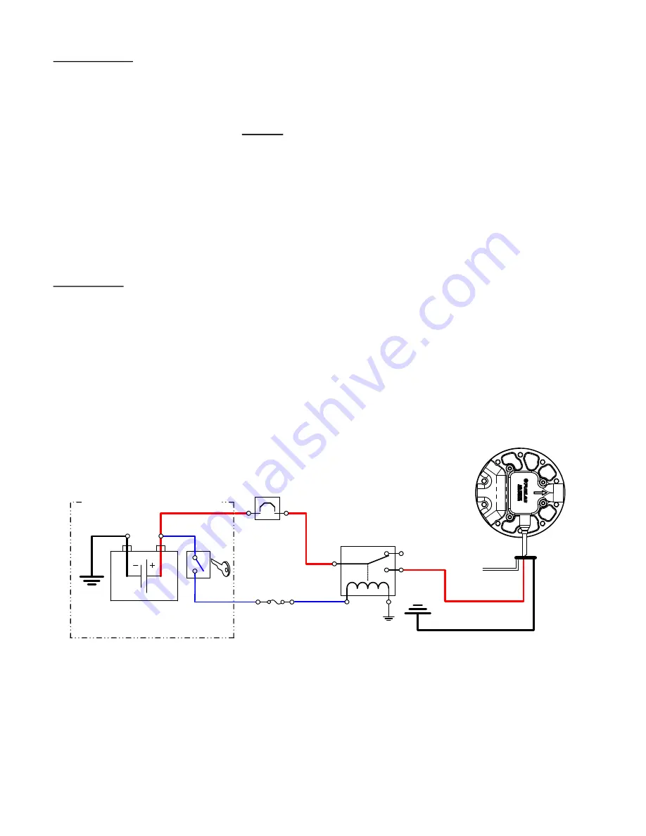
Reference below, for schematic wiring diagram example. Use electrical components as described including
electrical connectors that are appropriate for the operating environment of the fuel system, whether its use in street,
racing, or marine applications. Electrical connectors for the power leads must be capable of high current draw,
note all connections, wire and component rating requirements herein. Solder and use shrink wrap for wire splices
for extra reliability. Main wiring schematic diagram below shows the control of relay by ignition switch. This source
can be changed as described, or by a toggle switch. Some forms of racing have specific rules regarding electrical
switching of fuel system. Consult appropriate racing guidelines, rules and regulations.
Speed Control: A “PWM (Pulse Width Modulation) Signal” is a signal that alternates between a “High” voltage level
that is limited to approximately 5 Volts to near 0 Volts or ground level (relative to the Power Ground Wire). The
signal shape is typically a square wave (when viewed on an oscilloscope) at a fixed frequency. This signal is
measured differentially between the PWM Signal (White) Wire and the Power Ground (Black) Wire. The ratio of the
signal being “High” vs. “Low” defines the “Dwell Time” in percentage. The Controller interprets a PWM signal’s
“Dwell Time” range between 5% and 95% to communicate pump flow performance between the minimum speed
available and the maximum speed available respectively. If the Controller fails to interpret or losses the signal, the
Controller will default to the maximum speed (or flow) setting. Electronic devices such as Engine Management
Units may have an output that can produce PWM Signals compatible with this Controller. Attach this white signal
wire to ground to operate system in Full Speed Mode (not using speed control).
MAIN WIRING SCHEMATIC DIAGRAM:
(Some electrical components shown are not supplied with kit)
110021253-1, No Rev Sheet 3 of 6
CIRCUIT
BREAKER
or FUSE
C
NO
NC
FUEL PUMP
POWER RELAY
VEHICLE BATTERY
VEHICLE ELECTRICAL SYSTEM
IGNITION
SWITCH
or ECM
(16-20ga)
(30+A RATING)
(20A)
(12-18 VOLT SYSTEM)
FUSED
CIRCUIT
(1-5A)
(12-14ga)
(12-
14ga)
(12-14ga) BLK
RED
(18ga)
WHT
To
PWM
Signal


